Method and system for video quality assessment

a video quality and video technology, applied in the field of video quality assessment, can solve problems such as production line testing, complex subjective testing, time-consuming, etc., and achieve the effect of improving video quality

Active Publication Date: 2006-07-13
BRITISH TELECOMM PLC
View PDF22 Cites 37 Cited by
  • Summary
  • Abstract
  • Description
  • Claims
  • Application Information

AI Technical Summary

Benefits of technology

[0007] The present invention addresses the above identified problem by providing a method and system for automated video quality assessment which reduces the adverse effects of sub-field / frame misalignments between the reference and test sequences. More particularly, the invention provides for misalignments down to a sub-field / frame level to be handled by individually matching sub-field / frame elements of a test video field / frame with sub-field / frame elements from a reference video field / frame. The use of a matching element size that is significantly smaller than the video field / frame size enables transient sub-field / frame misalignments to be effectively tracked.
[0011] The first aspect of the invention provides the advantages described above of allowing sub-field / frame misalignments and other artefacts to be accounted for, such that the overall video quality value is not affected by such misalignments. In this respect, the sub-field / frame elements are preferably sized so as to permit misalignments and other artefacts which are substantially perceptually unnoticeable to a human viewer to be matched.
[0012] In a preferred embodiment, the matching step preferably further comprises, for a sub-field / frame element of the test video field / frame, searching for a matching sub-field / frame element within M1 preceding and / or M2 succeeding reference video fields / frames to a temporally corresponding reference video field / frame to the test video field / frame, wherein M1 and M2 are integers. This allows for matches to be made between sub-elements not only within the temporally corresponding field / frame, but also or alternatively in temporally different fields / frames, thus allowing for temporal artefacts such as block freezing to be taken into account. Preferably the temporal search limits M1 and M2 are predefined, although in variations of the invention they may be adaptively defined.
[0014] In embodiments of the invention the matching step may preferably further comprise calculating one or more matching statistic values and / or matching vectors; and wherein the generating step generates the video quality parameter in further dependence on the calculated matching statistic values and / or matching vectors. The use of matching statistics from the matching step has been found to substantially improve the overall video quality value which is obtained, making it more similar to video quality values obtained from human subjective testing. The use of matching vectors has similarly been found to improve the overall video quality value.
[0023] By counting the number of edges within sub-elements of the fields / frames then imperceptible differences in edge position can be accounted for, resulting in an edge evaluation value which can be used to derive an improved video quality value which more closely resembles such a value as derived by human subjective testing.
[0024] Preferably, within the preferred embodiment the integrating step further comprises weighting each value by a predetermined weighting factor; and summing the weighted values to give the video quality value. The weighting factors are found by calibration in advance, and can be used to tune the overall integration of the various video characteristic values such that the final video quality value more closely resembles a value obtained from a human subjective test. Preferably the weighting factors and the offset value are dependent on the type of the test and reference video fields / frames, such that for each type of video field / frame weighting values specific to that type may be used. This allows the same advantages provided by the invention to be obtained with many different types of video.

Problems solved by technology

However, there are clear disadvantages in that the precise set up of the test can affect the result obtained, that meticulous set up and control are required, and that in order to obtain statistically significant results a great many human viewers must be selected and screened.
These disadvantages render subjective testing complex and time consuming, with the result that whilst subjective tests may be applicable for development purposes, they do not lend themselves to operational monitoring, production line testing, or the like.
Problems can arise, however, with straightforward comparisons of test and reference sequences to generate the quality metrics mentioned above.
For example, spatial or temporal misalignment between the whole or parts of the reference and the test sequence can greatly affect such measurements, but may be perceptually insignificant to a human viewer.
However, more complex, but equally imperceptible, misalignments may also occur within a field or frame, where different regions of a video field or frame might be subject to different shifts, scaling, or delay.

Method used


Image

  • Method and system for video quality assessment
  • Method and system for video quality assessment
  • Method and system for video quality assessment

Examples


Embodiment Construction

[0052] Embodiments of the present invention will now be described.

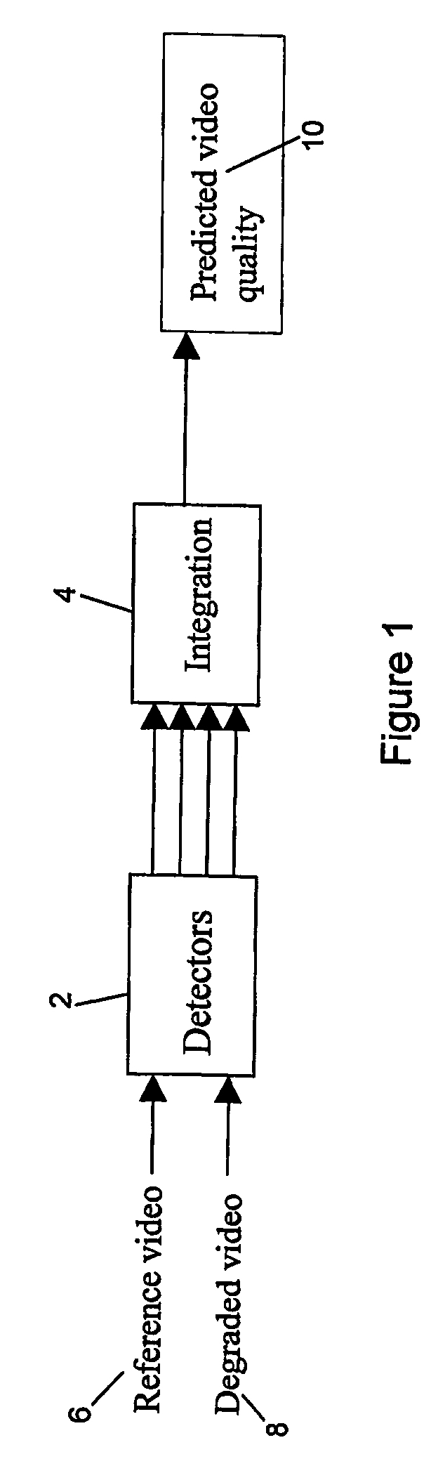
[0053]FIG. 1 illustrates an overall system block diagram of the general arrangement of the embodiments of the invention. Within FIG. 1 a reference sequence comprising reference sequence fields / frames is input to a detector module 2. Similarly, a test sequence of video fields / frames 8 (interchangeably referred to herein as either the test sequence, or the degraded sequence) is also input in to the detector module 2. The test sequence is obtained by inputting the reference sequence to a system to be tested (such as a video recording device, a broadcast system, or a video codec, for example), and then taking the output of the system under test as the test sequence. The detector module 2 acts to detect various video characteristics of the input reference and test video fields / frames and generates video characteristic values which are then output to an integration module 4. The integration module 4 integrates the video ch...


PUM


Abstract

A method and system for automated video quality assessment which reduces the adverse effects of sub-field / frame misalignments between the reference and test sequences. More particularly, the invention provides for misalignments down to a sub-field / frame level to be handled by individually matching sub-field / frame elements of a test video field / frame with sub-field / frame elements from a reference video field / frame. The use of a matching element size that is significantly smaller than the video field / frame size enables transient sub-field / frame misalignments to be effectively tracked.

Description

TECHNICAL FIELD [0001] The present invention relates to a method and system for video quality assessment, and in particular to a method and system wherein a video quality assessment value is generated in dependence on sub-field / frame elements. BACKGROUND TO THE INVENTION AND PRIOR ART [0002] Video quality testing has been performed for many years. Prior to the advent of digital compression techniques for video, formal subjective testing had been used with a relatively stable set of standard methods. In brief, a number of non-expert observers are selected, tested for their visual capabilities, shown a series of tests scenes for about 10 to 30 minutes in a controlled environment, and asked to score the quality of the scenes in one of a variety of manners. Usually, for full reference testing, the reference sequence is shown first, followed by the sequence under test, and the viewer is asked to rate the sequence under test with respect to the reference sequence. Further details of subje...

Claims


Application Information

Patent Timeline
Patent Type & Authority Applications(United States)
IPC IPC(8): G01R29/26H04N17/00H04N17/02
CPCG06T7/001H04N17/004H04N17/02H04N17/00G06T7/00
Inventor BOURRET, ALEXANDREJHANDS, DAVIDSBAYART, DAMIENDAVIS, ANDREWG
Owner BRITISH TELECOMM PLC
Why Eureka
Try Eureka