Ball joint

a ball joint and ball joint technology, applied in the field of ball joints, can solve the problems of excessive stress of the bellows seal, the failure of the ball joint to wear out, and the premature wear of the ball joint, and achieve the effect of large angular deflection reliably possibl

Inactive Publication Date: 2011-02-03
ZF FRIEDRICHSHAFEN AG
View PDF17 Cites 0 Cited by
  • Summary
  • Abstract
  • Description
  • Claims
  • Application Information

AI Technical Summary

Benefits of technology

[0005]The object of the invention is to provide a ball joint for a motor vehicle, the bellows seal of which makes large angular deflections reliably possible over a long life cycle without being subject to increased wear.

Problems solved by technology

Therefore, the bellows seal even with such an implementation of a ball joint tends to wear prematurely.
Due to the increased angular deflection, in comparison to known ball joint implementations realized with the ball joint, the bellows seal is excessively stressed.
If the bellows seal is then no longer able to lift off from the housing this leads to a tendency to break in the developing fold sections, which ultimately leads to permanent damage to the bellows seal.

Method used


Image

  • Ball joint
  • Ball joint
  • Ball joint

Examples


Embodiment Construction

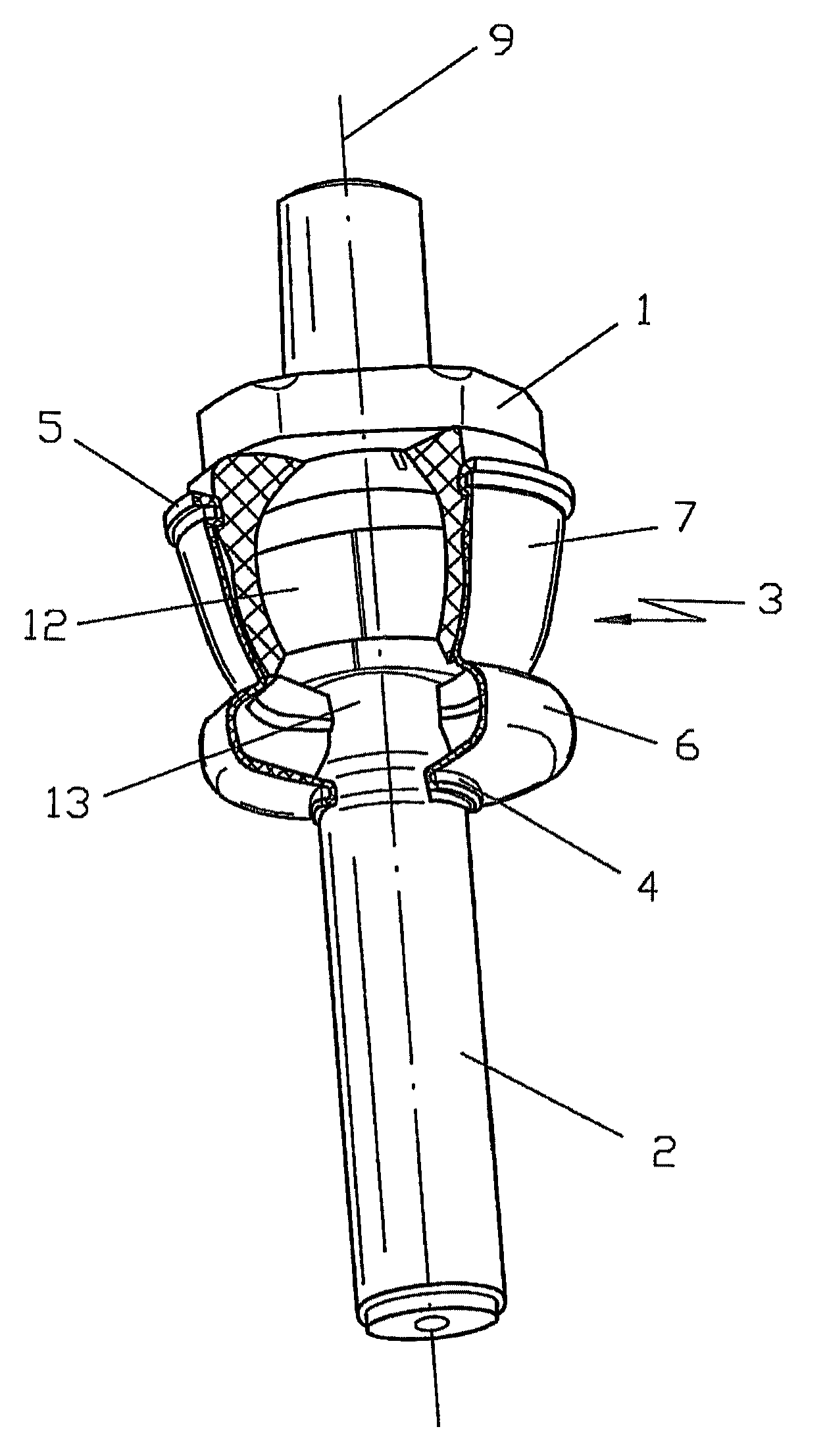
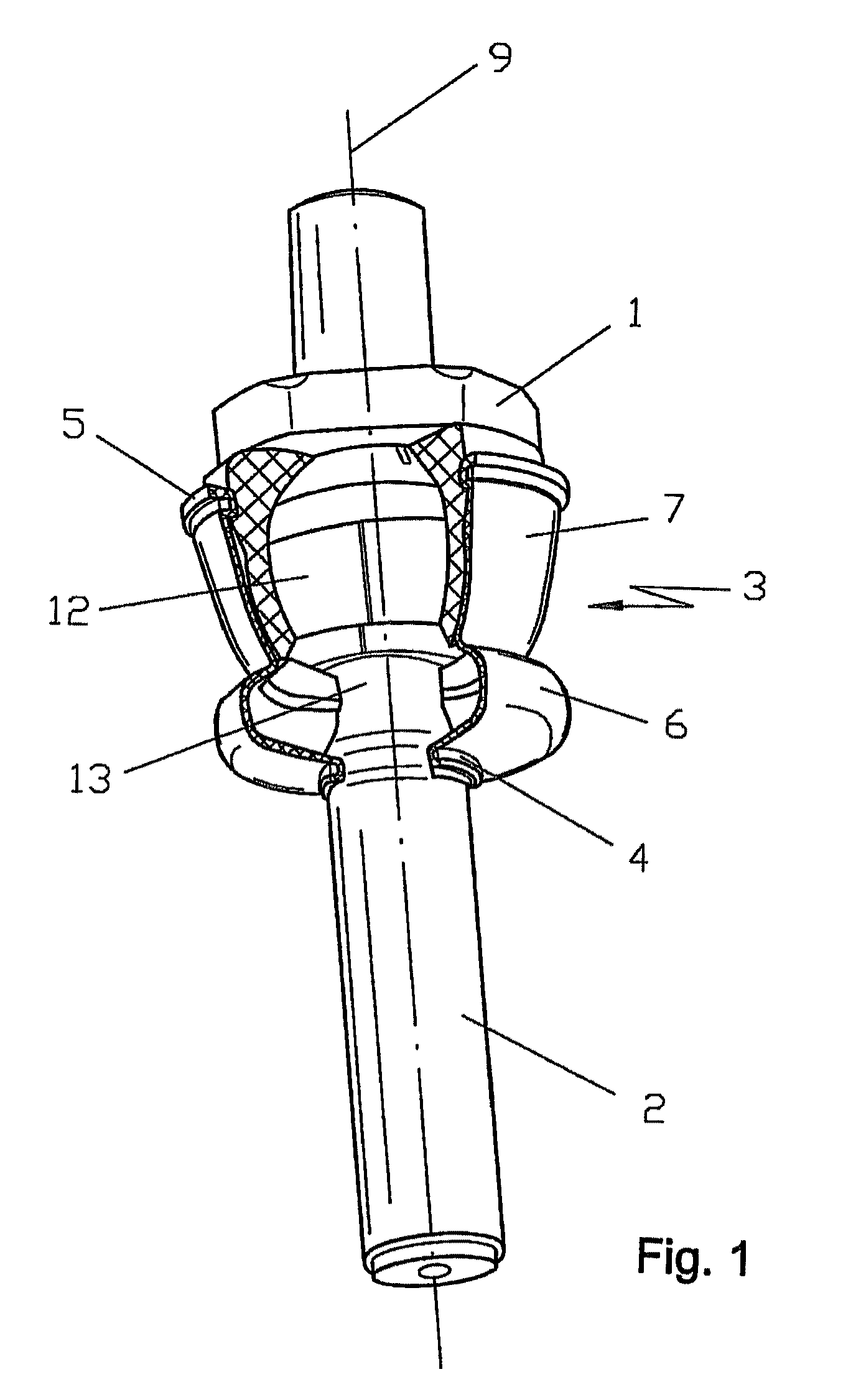
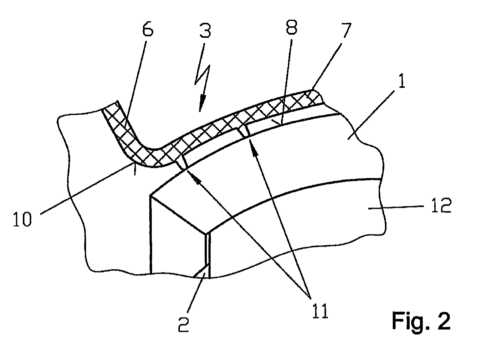
[0020]The ball joint shown in FIG. 1 has a housing 1. A ball pin 2 is rotatably and pivotably supported in the housing 1. For improved bearing properties the ball joint according to the illustration has a bearing shell 12 that with its inner surface area receives the joint ball of the ball pin 2 and with its outer surface is inserted directly in the housing 1 of the ball joint. In addition, the ball joint has a bellows seal 3 that with a first bellows seal edge 4 rests in a sealing manner directly on the pin-shaped section of the ball pin 2. On the side opposite of this first bellows seal edge 4, the bellows seal 3 has a second bellows seal edge 5 that is inserted into a corresponding groove-shaped recess in the housing 1 forming a seal, and is fixed to the housing 1 by a clamping ring, not shown in more detail. The first bellows seal edge 4 is also fastened by means of a clamping ring to the ball pin 2. The overall one-piece bellows seal 3 has two sections 6 and 7 that differ in th...


PUM


Abstract

A ball joint for a motor vehicle. The ball joint has a housing, a ball pin that is supported within the housing in a rotatable and pivotal manner, and a bellows seal. The bellows seal rests with a first bellows seal edge in a sealing manner against the ball pin, and with a second bellows seal edge rests in a sealing manner against the housing. The one-piece bellows seal comprises at least first and second sections, between its bellows seal edges, having different geometries, of which a first section forms a round bodied contour and a second section has an extension along the outer surface and in the direction of the longitudinal axis of the housing. The inner surface of the second section of the bellows seal and/or the outer surface of the housing corresponding thereto is provided with a surface geometry having alternating directions.

Description

[0001]This application is a National Stage completion of PCT / DE2009 / 050014 filed Apr. 2, 2009, which claims priority from German patent application serial no. 10 2008 000 996.2 filed Apr. 4, 2008.FIELD OF THE INVENTION[0002]The invention relates to a ball joint.BACKGROUND OF THE INVENTION[0003]A ball joint for a motor vehicle having a housing and a ball pin which is rotatably and pivotably supported in the housing, and also having a bellows seal is known from DE 195 45 567 A1. According to the disclosure in this publication, the bellow seal rests with a first edge of the bellows seal in a sealing manner on the ball pin and with a second edge of the bellows seal in a sealing manner on the housing, wherein the bellows seal implemented overall as one-piece has at least two sections of different geometry between its bellows seal edges, of which a first section forms a round bodied contour and a second section has an extension along the outer surface and in the direction of the longitudi...

Claims


Application Information

Patent Timeline
Patent Type & Authority Applications(United States)
IPC IPC(8): F16C11/06
CPCF16C11/0628Y10T403/32729F16C11/0671
Inventor SOKOLIHS, DIRKGRUNDMANN, FRANKAHLERT, SONJA
Owner ZF FRIEDRICHSHAFEN AG
Why Eureka
Try Eureka