Torque transducer
a torsion transducer and torque technology, applied in the direction of instruments, force/torque/work measurement apparatus, measurement devices, etc., can solve the problems of slowness and more prone to error, space and cost, and device is prone to error, so as to limit the maximum angular deflection of torsionally compliant coupling
- Summary
- Abstract
- Description
- Claims
- Application Information
AI Technical Summary
Benefits of technology
Problems solved by technology
Method used
Image
Examples
first embodiment
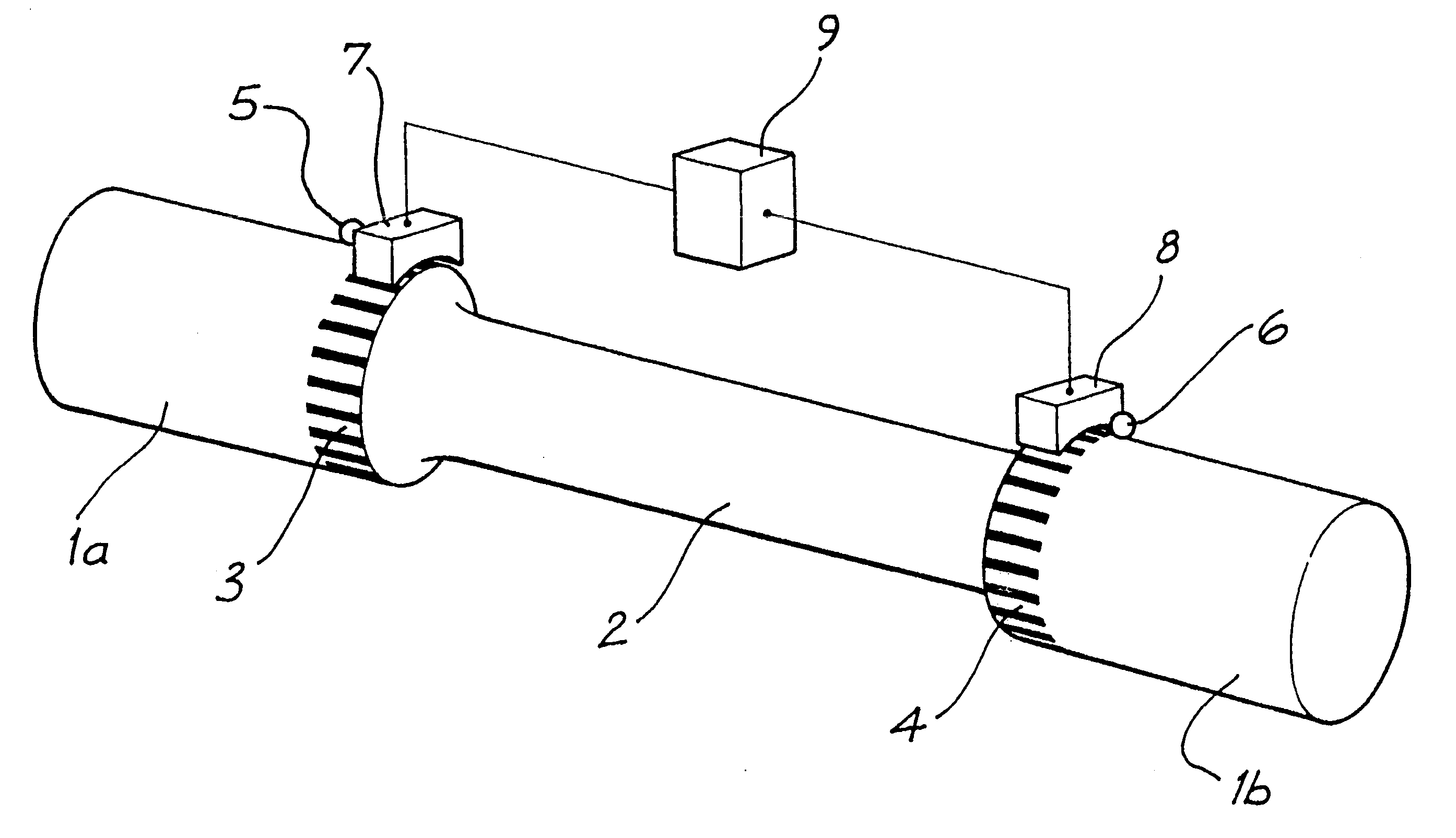
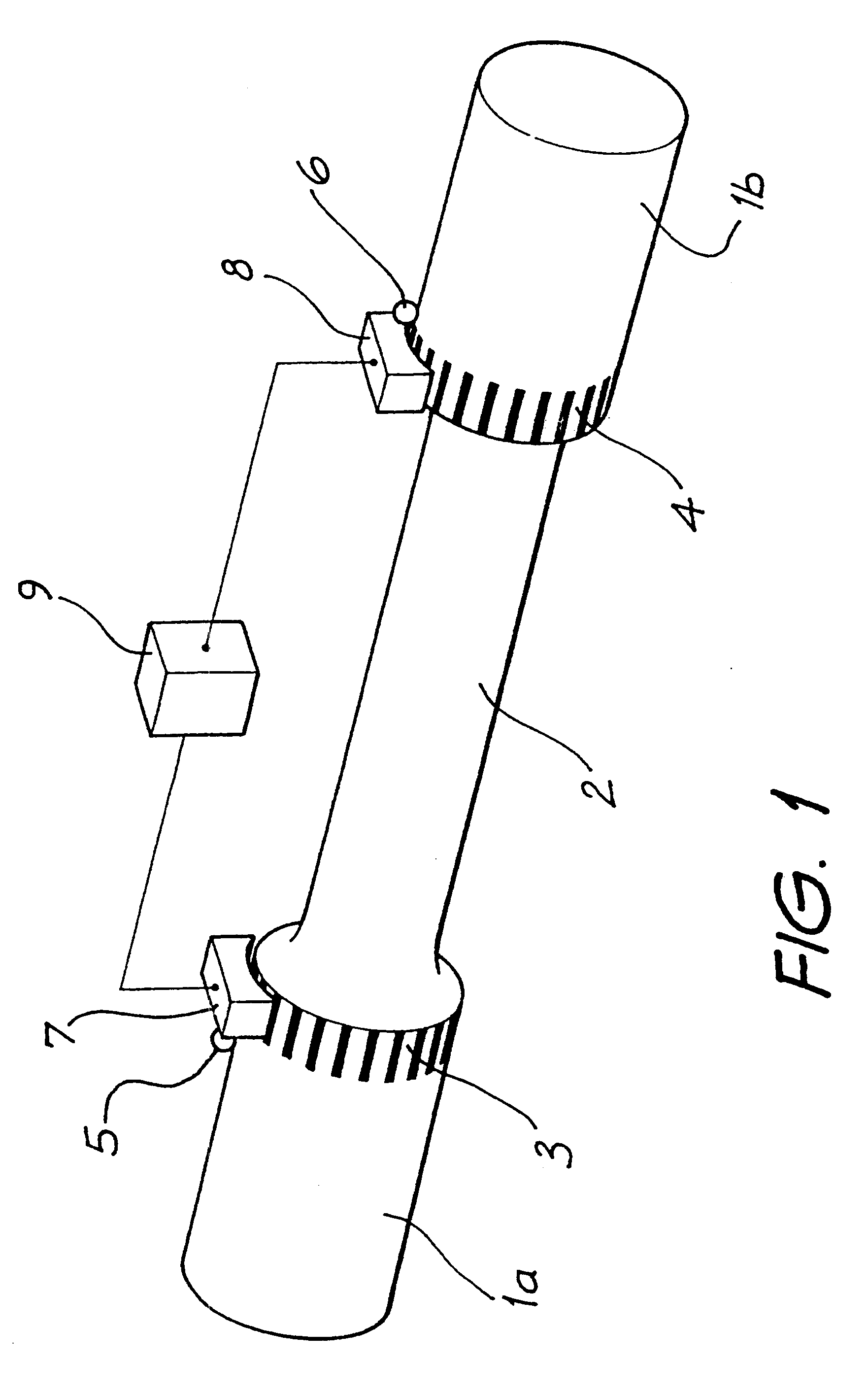
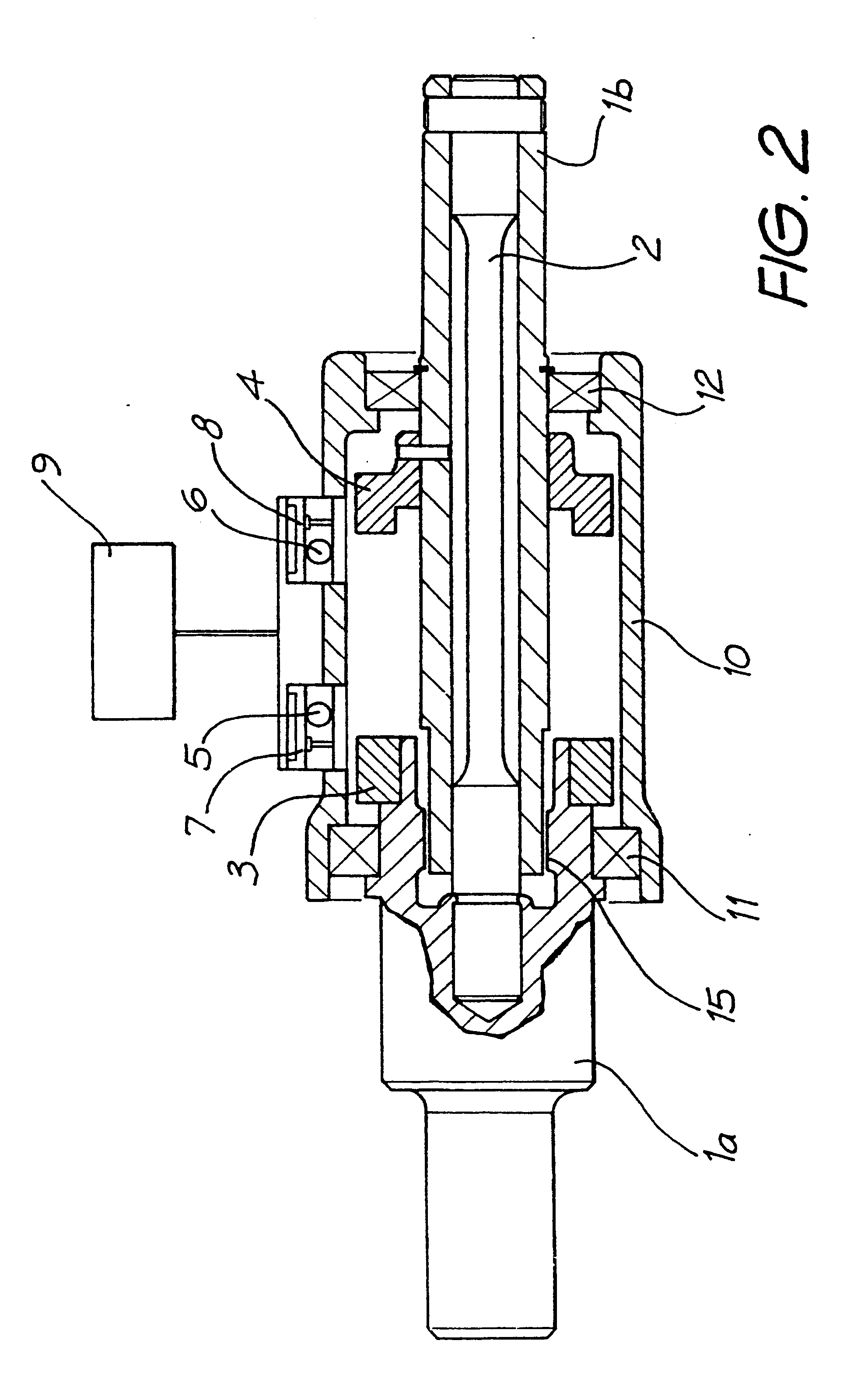
FIG. 2 shows a cross section of a torque transducer according to the present invention, using the principles shown in FIG. 1. Cylindrical grating elements 3 and 4, comprising surfaces composed of alternating high and low reflectivity, are attached to torque input members 1a and 1b which are connected to either end of the torsion bar 2. In other (not shown) embodiments either (or both) grating elements may be integral with their respective torque input members. The assembly is enclosed in housing 10 and supported by bearings 11 and 12. EMR sources 5 and 6 are disposed to illuminate the surfaces. Arrays 7 and 8 of detectors receive incident EMR from the surfaces and the patterns thus generated on the arrays are processed by a processor 9 to provide a measurement of torque. When torque is applied between torque input members 1a and 1b torsion bar 2 angularly deflects, resulting in a displacement of one pattern with respect to the other. Failsafe mechanism 15 limits the maximum torque c...
second embodiment
FIGS. 4, 5 and 6 shows the present invention. Cylindrical grating elements 21 and 22 are attached to torque input members 1a and 1b, connected to either end of the torsion bar 2. The outer cylindrical surfaces of grating elements 21 and 22 are discontinuous and are formed in part by substantially axially aligned, radially protruding castellations 13 and 14 respectively. The regions of high reflectivity correspond to the areas of maximum radius of the castellations with respect to their mutual central axis 16, that is outer peripheral areas 13a and 14a respectively, and may be smoothly machined, moulded or sintered, or surface treated with paint or material deposition to impart the required high reflectivity. The regions of low reflectivity are angularly aligned with the discontinuous gap areas of the outer cylindrical surfaces of grating elements 21 and 22, namely areas 13b and; 14b respectively and, in the embodiment shown here, are substantially non-reflective due to the presence ...
third embodiment
FIGS. 8 and 9 show the present invention. Cylindrical grating elements 25 and 26, each comprising a substantially smooth cylindrical surface with alternating regions of high and low reflectivity, are respectively attached to torque input members 1a and 1b, which in turn are connected to either end of torsion bar 2. This assembly is enclosed in housing 10 and supported by bearings 11 and 12. A metallised coating, or other shiny or light coloured material or surface treatment, provides substantially axially aligned regions of high reflectivity, 25a and 26a. A substantially transparent, roughened or dark coloured material or surface treatment provides the, interspaced regions of low reflectivity 25b and 26b. EMR source 19 is arranged to illuminate both surfaces, and the array 20 of detectors receives incident EMR from the surfaces and the pattern thus generated on the array is processed by processor 9 to provide a measurement of torque. Failsafe mechanism 15, shown in cross section in ...
PUM
| Property | Measurement | Unit |
|---|---|---|
| angle | aaaaa | aaaaa |
| angle | aaaaa | aaaaa |
| length | aaaaa | aaaaa |
Abstract
Description
Claims
Application Information
 - R&D
- Intellectual Property
- Life Sciences
- Materials
- Tech Scout
- Unparalleled Data Quality
- Higher Quality Content
- 60% Fewer Hallucinations
Browse by: Latest US Patents, China's latest patents, Technical Efficacy Thesaurus, Application Domain, Technology Topic, Popular Technical Reports.
© 2025 PatSnap. All rights reserved.Legal|Privacy policy|Modern Slavery Act Transparency Statement|Sitemap|About US| Contact US: help@patsnap.com


