Vibration damping device for a motor vehicle transmission drivetrain

a technology of vibration damping and transmission drivetrain, which is applied in the direction of mechanical equipment, low internal friction springs, and gear details, etc., can solve the problems of limited angular deflection of damping devices as described in the document fr 3000155, and the filtering performance of damping devices as described, so as to reduce angular stiffness and increase filtering performance

Active Publication Date: 2017-12-21
VALEO EMBRAYAGES SAS
View PDF1 Cites 2 Cited by
  • Summary
  • Abstract
  • Description
  • Claims
  • Application Information

AI Technical Summary

Benefits of technology

[0013]the damping device further having a rolling body movable with respect to the second element so that a curvilinear trajectory can be executed on at least a predetermined angular sector (A), the curvilinear movement of the rolling body with respect to the second element being accompanied by a movement of the rolling body on the elastic blade, causing the latter to flex.
[0014]The movability of the rolling body with respect to the second element thus allows an increase in the maximum angular deflection between the first and the second element with respect to a damping device of the equivalent existing art in which the roller that interacts with the elastic blade is fastened on one of the input or output elements. A damping device of this kind thus makes it possible to decrease the angular stiffness for a given maximum torque to be transmitted, thus resulting in a significant increase in filtering performance.
[0015]Torque is furthermore transmitted between the first element and the second element by means of the rolling body, without passing through a support shaft capable of deforming. Such a configuration thus makes it possible to implement a particularly robust vibration damping device.
[0020]The distances covered by the rolling body on the first raceway and on the second raceway are thus the same, so that the maximum angular deflection between the first and the second element is substantially doubled with respect to a damping device of the equivalent existing art in which the roller, interacting with the elastic blade, would be fastened on one of the input or output elements. A damping device of this kind thus makes it possible to decrease the angular stiffness for a given maximum torque to be transmitted, which results in a significant increase in filtering performance.
[0021]In a damping device of this kind the characteristic curve, i.e. the curve representing the change in transmitted torque as a function of angular movement, furthermore depends both on the geometry of the first raceway and on that of the second raceway, while in a blade-type damping device according to the existing art it depends only on the geometry of the cam carried by the blade. A configuration of this kind is thus capable of offering a wider variety of curves for torque transmission as a function of deflection.
[0035]The damper has at least one anti-slip means preventing slippage of the rolling body on the raceways.

Problems solved by technology

The angular deflection of a damping device as described in the document FR 3000155 remains limited, however, given the constraints associated with the physical size of the blades.
The shape of the blade is subject to numerous other design constraints, however, such as the physical size and stiffness of the blade, so that certain curves for torque transmission as a function of angular deflection cannot be implemented.
The filtering performance of a damping device as described in the aforementioned document FR3000155 is therefore not entirely satisfactory.

Method used


Image

  • Vibration damping device for a motor vehicle transmission drivetrain
  • Vibration damping device for a motor vehicle transmission drivetrain
  • Vibration damping device for a motor vehicle transmission drivetrain

Examples


Embodiment Construction

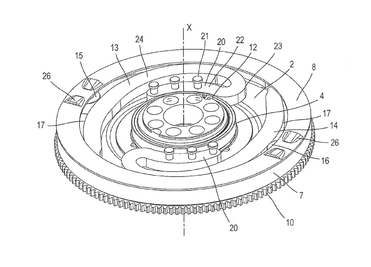
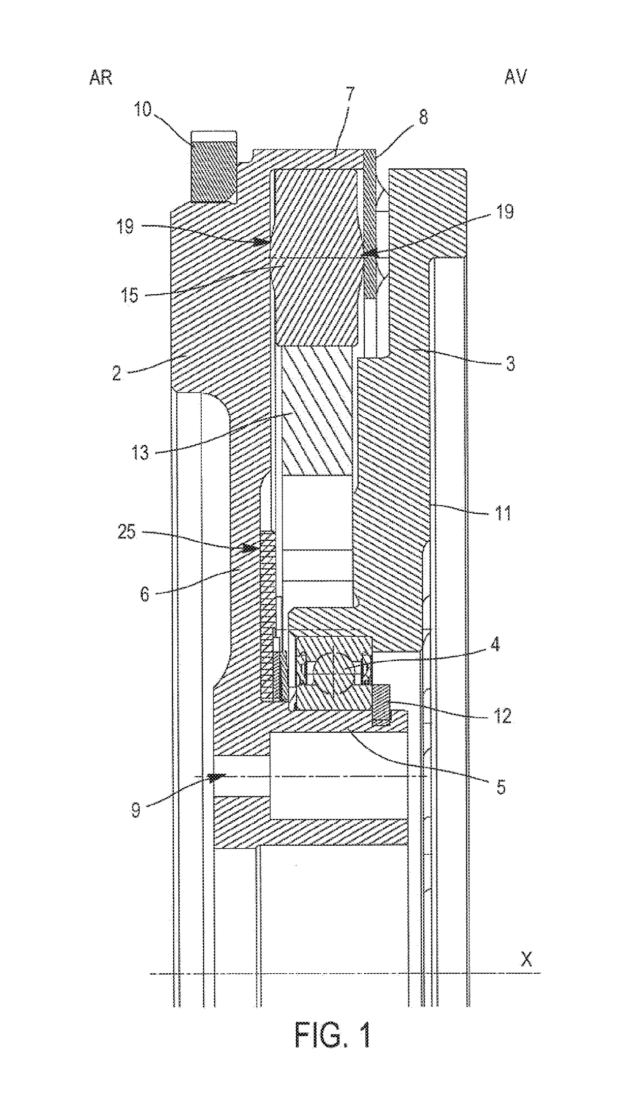
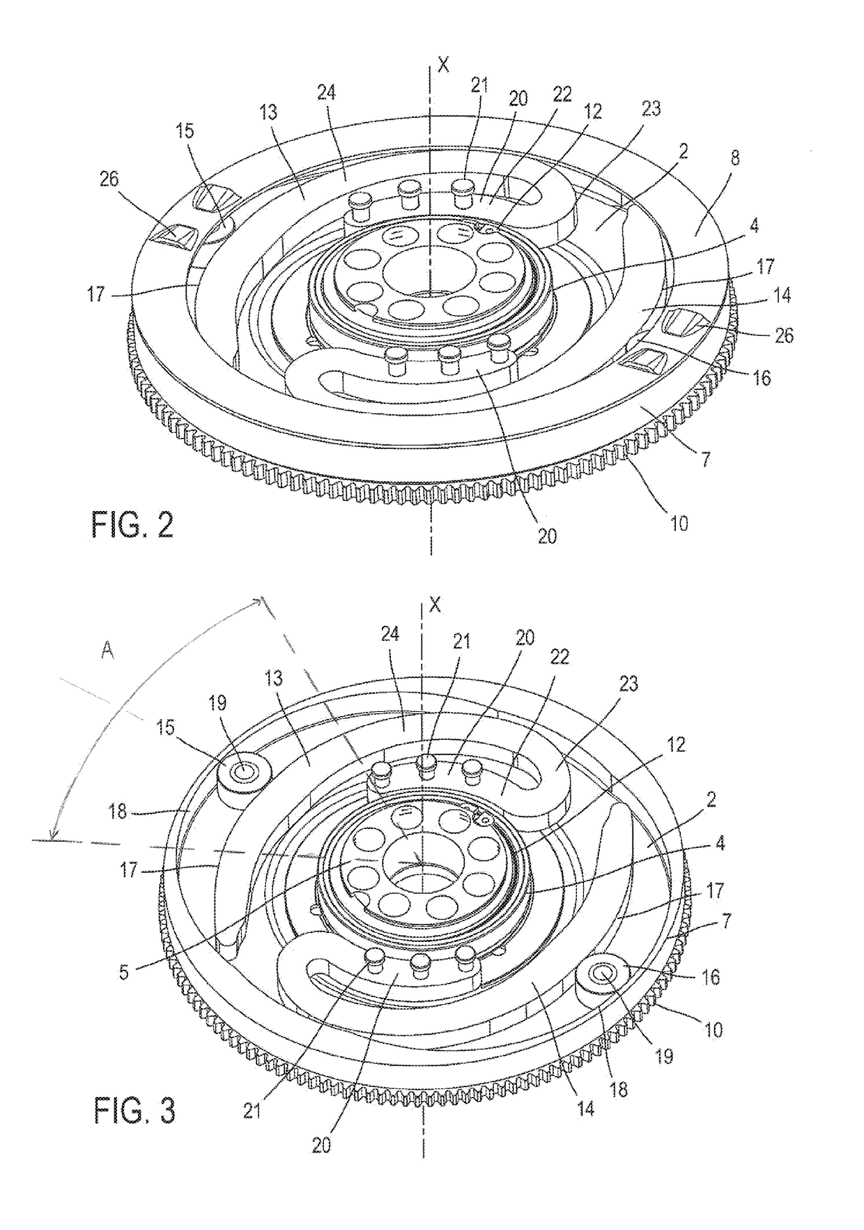
[0067]In the description and the claims, the terms “outer” and “inner,” as well as the “axial” and “radial” orientations, will be used to designate elements of the vibration damping device in accordance with the definitions given in the description. By convention, the “radial” orientation is directed orthogonally to the rotation axis X of the damping device which determines the “axial” orientation; and, moving away from said axis from inside to outside, the “circumferential” orientation is directed orthogonally to the axis of the damping device and orthogonally to the radial direction. The terms “outer” and “inner” are used to define the relative position of one element with respect to another with reference to the rotation axis X of the damping device; an element close to the axis is thus categorized as “inner” as opposed to an “outer” element situated radially at the periphery. The terms “rear” (AR) and “front” (AV) are also used to define the relative position of one element with...


PUM


Abstract

The invention relates to a device for damping vibrations, for a motor vehicle transmission drivetrain, comprising:a first element and a second element (2) that are rotationally movable around a rotation axis X;elastic damping means having an elastic blade (13, 14) mounted rotationally integrally with the first element (3); anda rolling body movable with respect to the second element so that a curvilinear trajectory can be executed on at least a predetermined angular sector (A), the curvilinear movement of the rolling body with respect to the second element being accompanied by a movement of the rolling body on the elastic blade, causing the latter to flex.

Description

TECHNICAL FIELD[0001]The invention relates to the field of devices for damping (in particular, torsional) vibrations, intended to be installed in motor vehicle transmissions.BACKGROUND OF THE INVENTION[0002]Motor vehicle transmissions are generally equipped with a damping device allowing vibrations to be filtered out upstream from the gearbox, so as to avoid shocks, noise, or acoustic impacts that are particularly undesirable. Damping devices of this kind are installed in particular in dual mass flywheels (DMFs) and / or friction clutches in the case of a manual or automated transmission, or in lock-up clutches that are installed in hydraulic coupling devices, in the case of an automatic transmission.[0003]The damping devices have elastic damping means that rotationally couple a torque input element and torque output element so as to allow transmission of a torque and damping of rotational irregularities.[0004]The document FR3000155 discloses a damping device in which the elastic damp...

Claims


Application Information

Patent Timeline
Patent Type & Authority Applications(United States)
IPC IPC(8): F16F15/133F16F3/02F16F15/131F16H57/00
CPCF16F15/1336F16F15/13157F16H2057/0012F16H57/0006F16F3/023F16F15/1333F16F2230/0064
Inventor DUTIER, IVANBOULET, JEROMEMAUREL, HERVE
Owner VALEO EMBRAYAGES SAS
Why Eureka
Try Eureka