Optical disk drive device

a technology of optical disk drive and clamping mechanism, which is applied in the direction of data recording, recording on magnetic disk, instruments, etc., can solve the problems of affecting the normal operation of the optical disk drive device, reducing the clamping force, and difficult to keep a concentric position between the optical disk and the spindle motor, so as to achieve smooth detachment of the clamper and improve the effect of unclamping structur

Inactive Publication Date: 2011-02-03
LG INNOTEK CO LTD
View PDF5 Cites 1 Cited by
  • Summary
  • Abstract
  • Description
  • Claims
  • Application Information

AI Technical Summary

Benefits of technology

[0008]The present invention provides an optical disk drive device configured to dispense with an excessive burden onto a deck during unclamping, and to smoothly detach the clamper from a spindle motor through improvement of an unclamping structure.

Problems solved by technology

However, in a case the magnetic clamping force is overpowered, it takes considerable energy to detach the clamper from a spindle motor during unclamping, resultantly disturbing the normal operation of the optical disk drive device.
On the other hand, in a case the magnetic force acting between the clamper and the spindle motor is reduced to perform a smooth unclamping, the clamping force decreases to make it difficult to keep a concentric status to the optical disk and the spindle motor.

Method used


Image

  • Optical disk drive device
  • Optical disk drive device
  • Optical disk drive device

Examples


Embodiment Construction

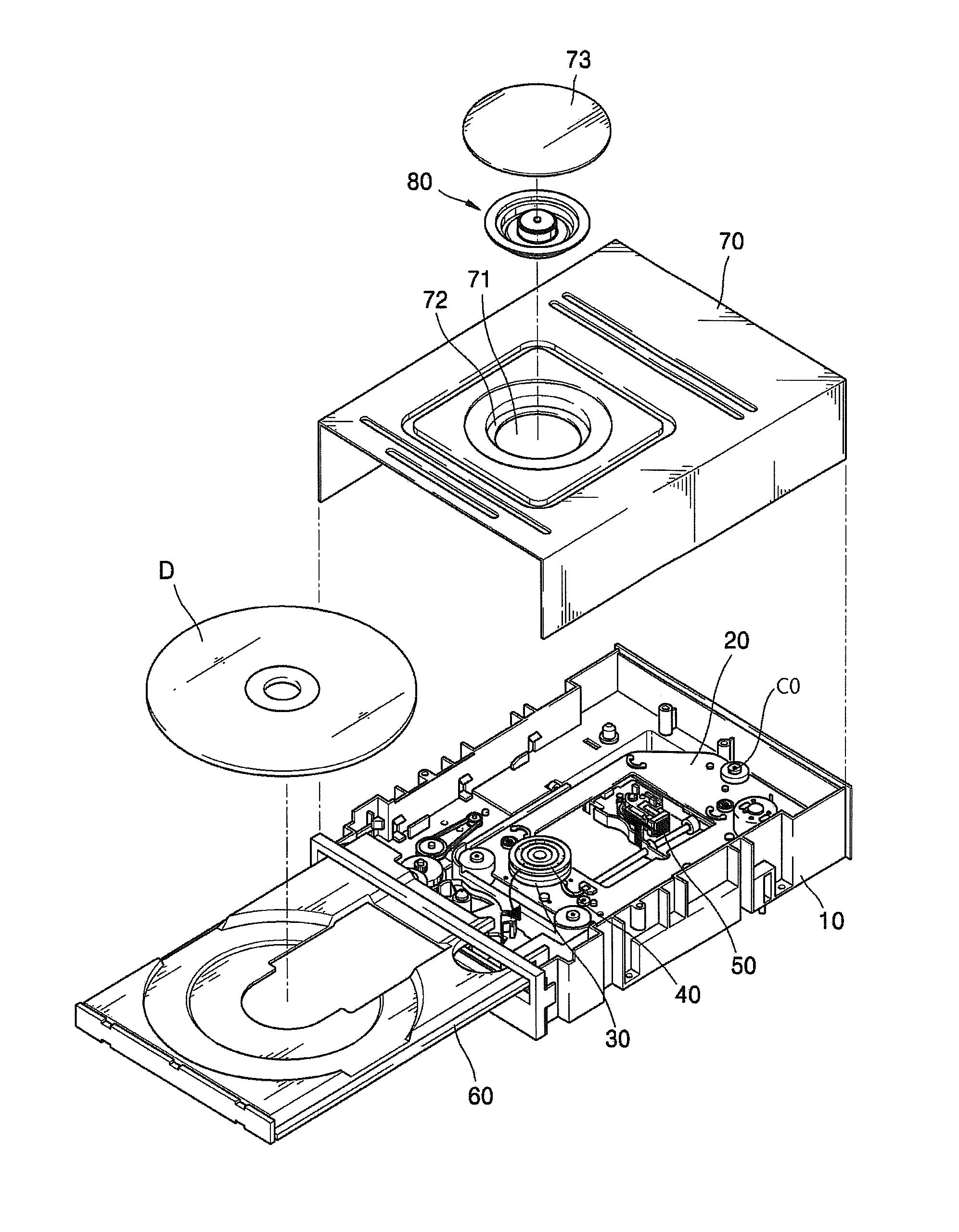
[0014]FIG. 1 is an exploded perspective view illustrating an optical disk drive device of the invention.

[0015]Referring to FIG. 1, the optical disk drive device includes a main frame 10, an upper part case 70 coupled to an upper part of the main frame 10, and a tray 60 for transporting a disk D into the optical disk drive device.

[0016]The disk D transported by the tray 60 is safely placed on a turntable 40 installed at the upper part of a spindle motor 30. The turntable 40 is coupled to the rotation shaft of the spindle motor 30 and rotates the disk D while rotating together with the rotation shaft. The spindle motor 30 is installed at the deck 20 coupled to the main frame 10, and an optical pickup 50 is installed at the deck 20.

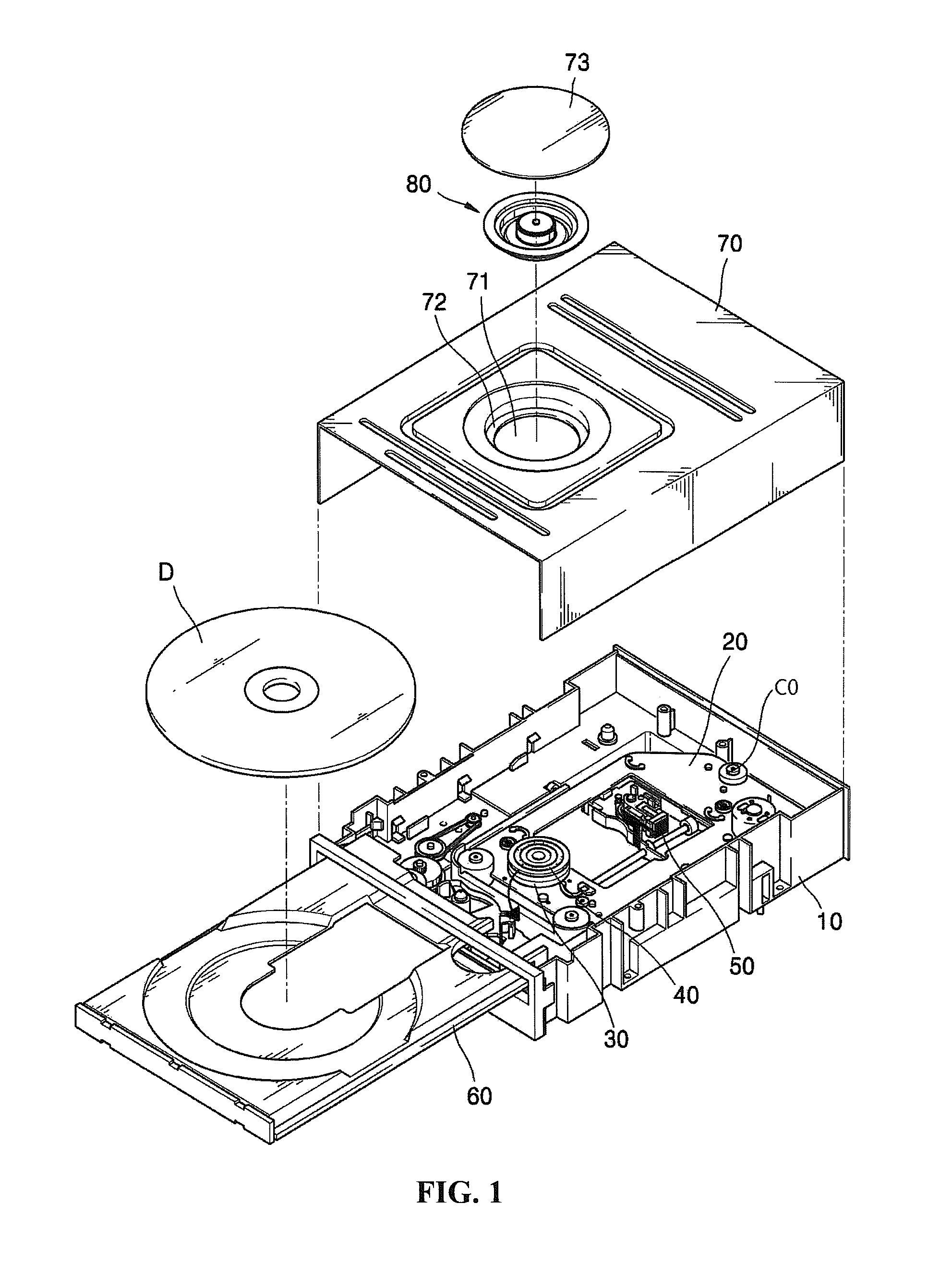
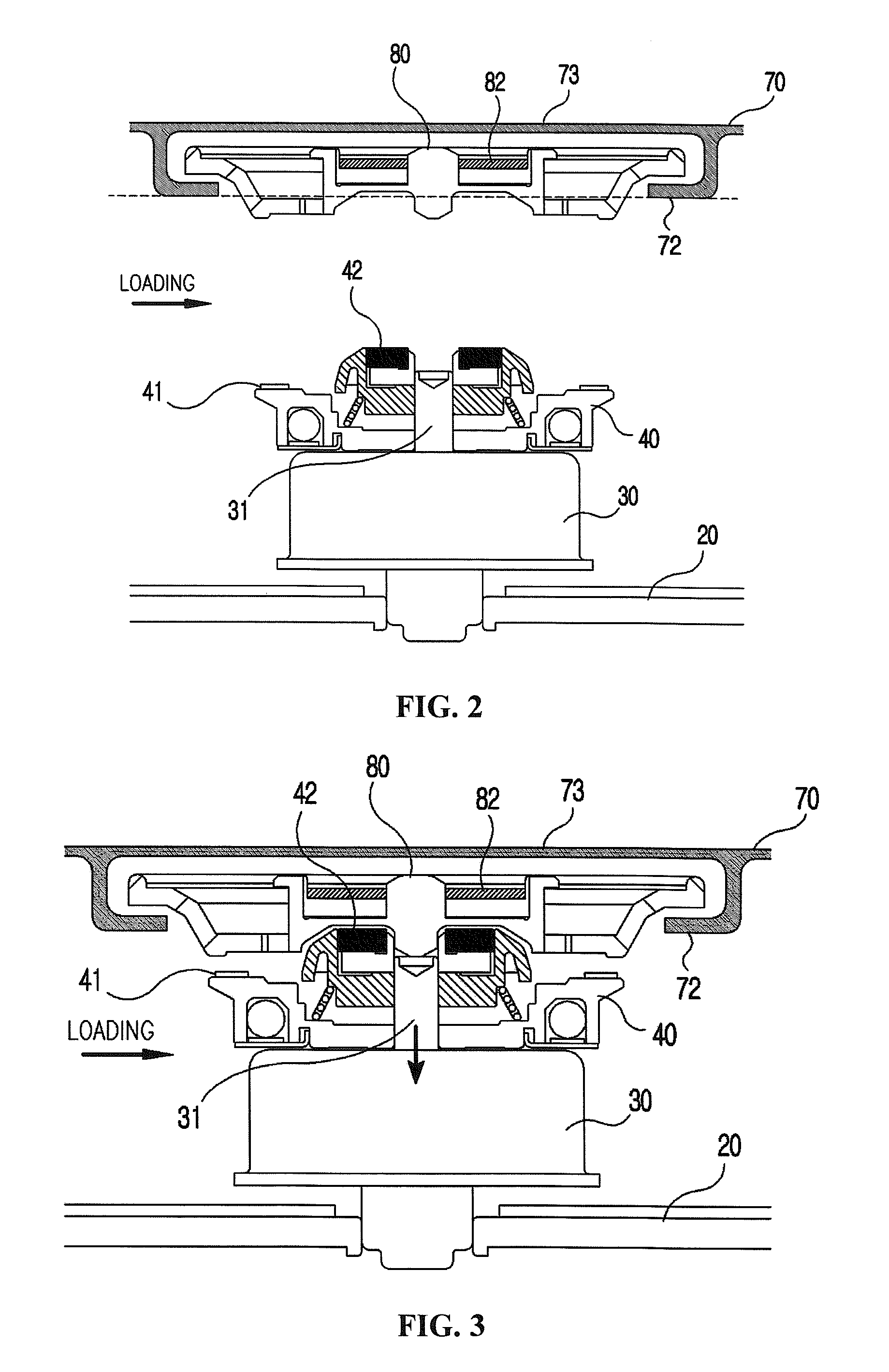
[0017]The optical disk drive device is provided with a clamping device clamping the disk D to the turntable 40 to inhibit the disk D from slipping on the rotation of the turntable 40.

[0018]As a clamping device, the clamper 80 fixing the disk D to the upper s...


PUM

PropertyMeasurementUnit
distanceaaaaaaaaaa
magnetic forceaaaaaaaaaa
magnetic clamping forceaaaaaaaaaa

Abstract

Disclosed herein is an optical disk drive device comprising an spindle motor rotating a turntable on which an optical disk is safely placed; a clamper adhering the optical disk to the turntable to clamp the optical disk into the turntable; and an upper case provided with a hollow part so opened as to make the clamper face the turntable, and a support part contacting and supporting the clamper as an edge of the hollow part, the support part being inclined against the turntable.

Description

CROSS-REFERENCE TO RELATED APPLICATION[0001]This application claims the benefit under 35 U.S.C. §119 of Korean Patent Application No. 10-2009-0068690, filed on Jul. 28, 2009, which is hereby incorporated by reference in its entirety.FIELD OF THE DISCLOSURE[0002]The present invention relates to an optical disk drive device.DESCRIPTION OF THE RELATED ART[0003]Generally, an ‘optical disk drive device’ refers to a device configured to write or reproduce data in an optical disk adapted to read or write any data by the illumination of light, for example CDs, DVDs, blue-ray DISCs, etc.[0004]The optical disk drive device includes an optical pickup for illuminating light onto an optical disk and processing an optical signal reflected from the optical disk, a main PCB processing the signal inputted / outputted from the optical pickup, a spindle motor for safely placing and rotating the optical disk, and a sled motor feeding the optical pickup in a radial direction of the optical disk.[0005]The ...

Claims


Application Information

Patent Timeline
Patent Type & Authority Applications(United States)
IPC IPC(8): G11B17/028
CPCG11B17/0284G11B17/056G11B17/0285G11B17/028G11B19/20G11B25/04
Inventor WOO, SHUNGHUN
Owner LG INNOTEK CO LTD
Why Eureka
Try Eureka