
Inertial Sensors with Reduced Sensitivity to Quadrature Errors and Micromachining Inaccuracies

a technology of quadrature errors and micromachining errors, applied in the field of micromachined inertial sensors, can solve the problems of asymmetry of sidewall angle produced, affecting the accuracy of micromachining, and imposing an almost impossible dynamic range requirement on the gyro electronics

Active Publication Date: 2011-02-10
ANALOG DEVICES INC
View PDF3 Cites 59 Cited by
  • Summary
  • Abstract
  • Description
  • Claims
  • Application Information

AI Technical Summary

Benefits of technology

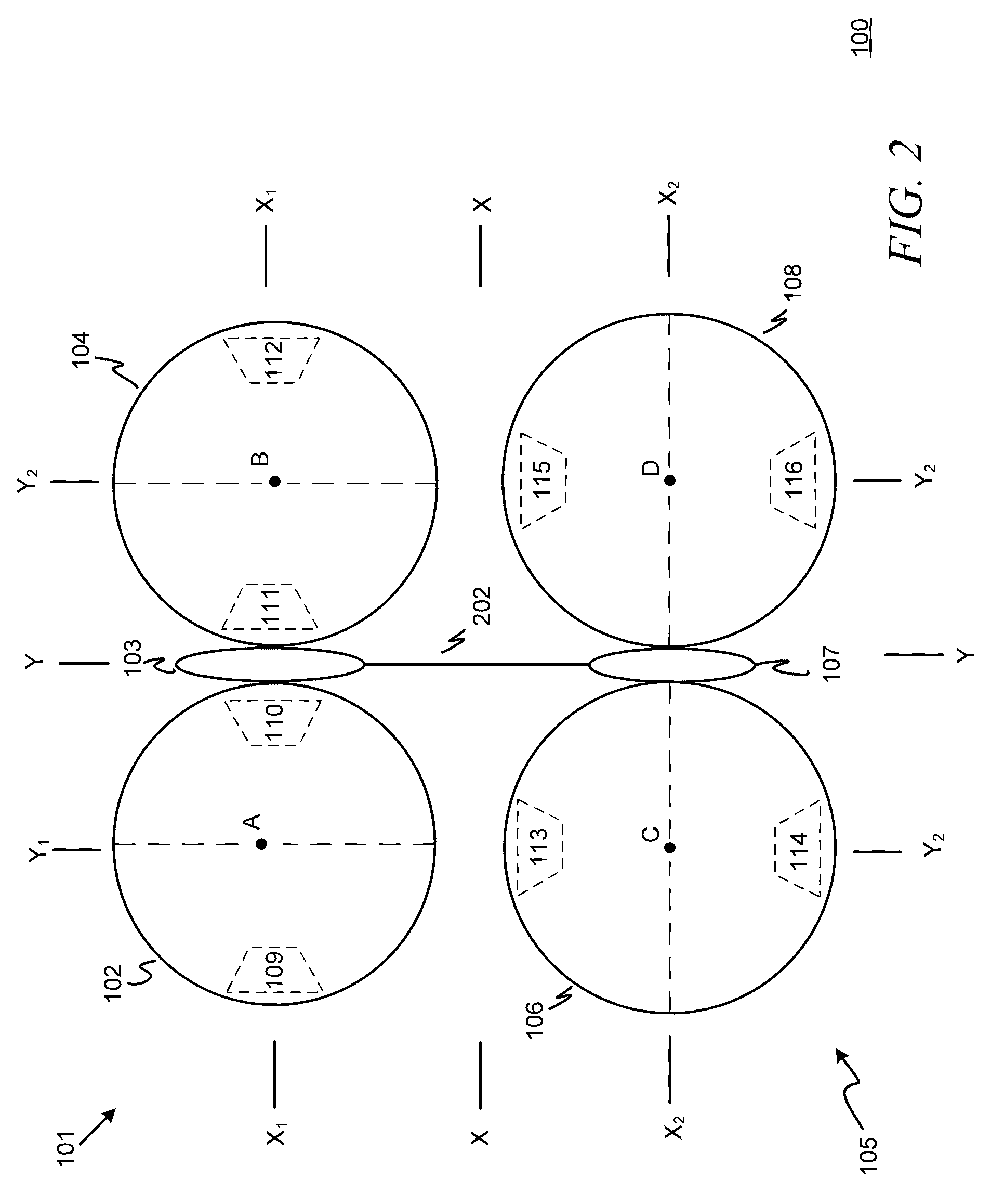
[0010]In accordance with another aspect of the invention there is provided a MEMS gyroscope comprising a first resonator configured for resonating in a device plane and sensing rotation about a first axis in the device plane; a second resonator configured for resonating in the device plane and sensing rotation about a second axis orthogonal to the first axis in the device plane; and at least one coupling interconnecting the first and second resonators, the at least one coupling configured to lock the resonance of the first and second resonators and to substantially prevent transfer of out-of-plane movements of each resonator to the other resonator.

Problems solved by technology

One of the more troubling manufacturing errors for micromachined gyroscopes is asymmetry of the sidewall angle produced during etching of the flexures.
Thus, the interfering signal is comparatively large and places an almost impossible dynamic range requirement on the gyro electronics.
However, the stability requirements of the trim and dynamic range of the servo are still very difficult electronics constraints with the tolerances accompanying high-speed mass production.

Method used


Image

  • Inertial Sensors with Reduced Sensitivity to Quadrature Errors and Micromachining Inaccuracies
  • Inertial Sensors with Reduced Sensitivity to Quadrature Errors and Micromachining Inaccuracies
  • Inertial Sensors with Reduced Sensitivity to Quadrature Errors and Micromachining Inaccuracies

Examples


Embodiment Construction

[0022]Definitions. As used in this description and the accompanying claims, the following terms shall have the meanings indicated, unless the context otherwise requires:

[0023]A “set” includes one or more members.

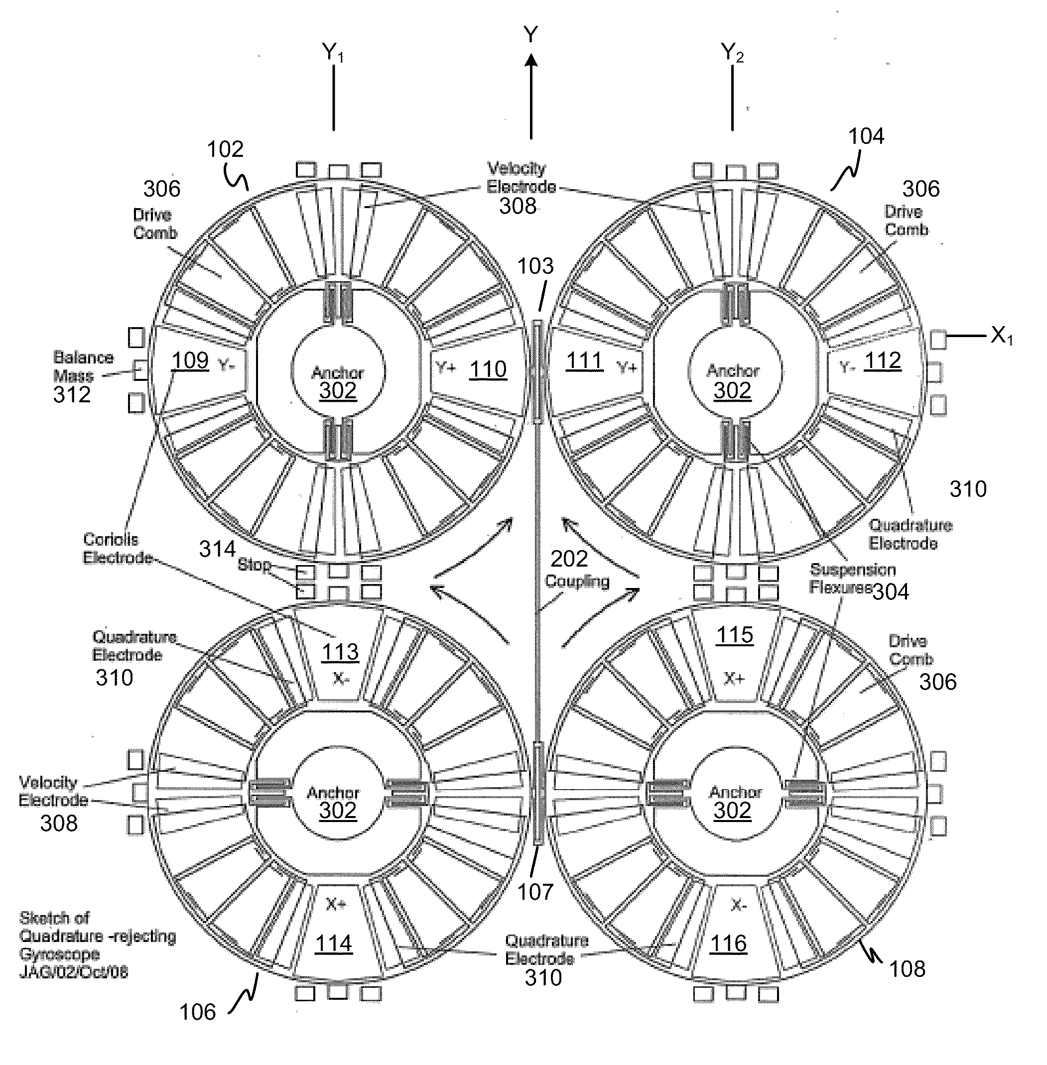
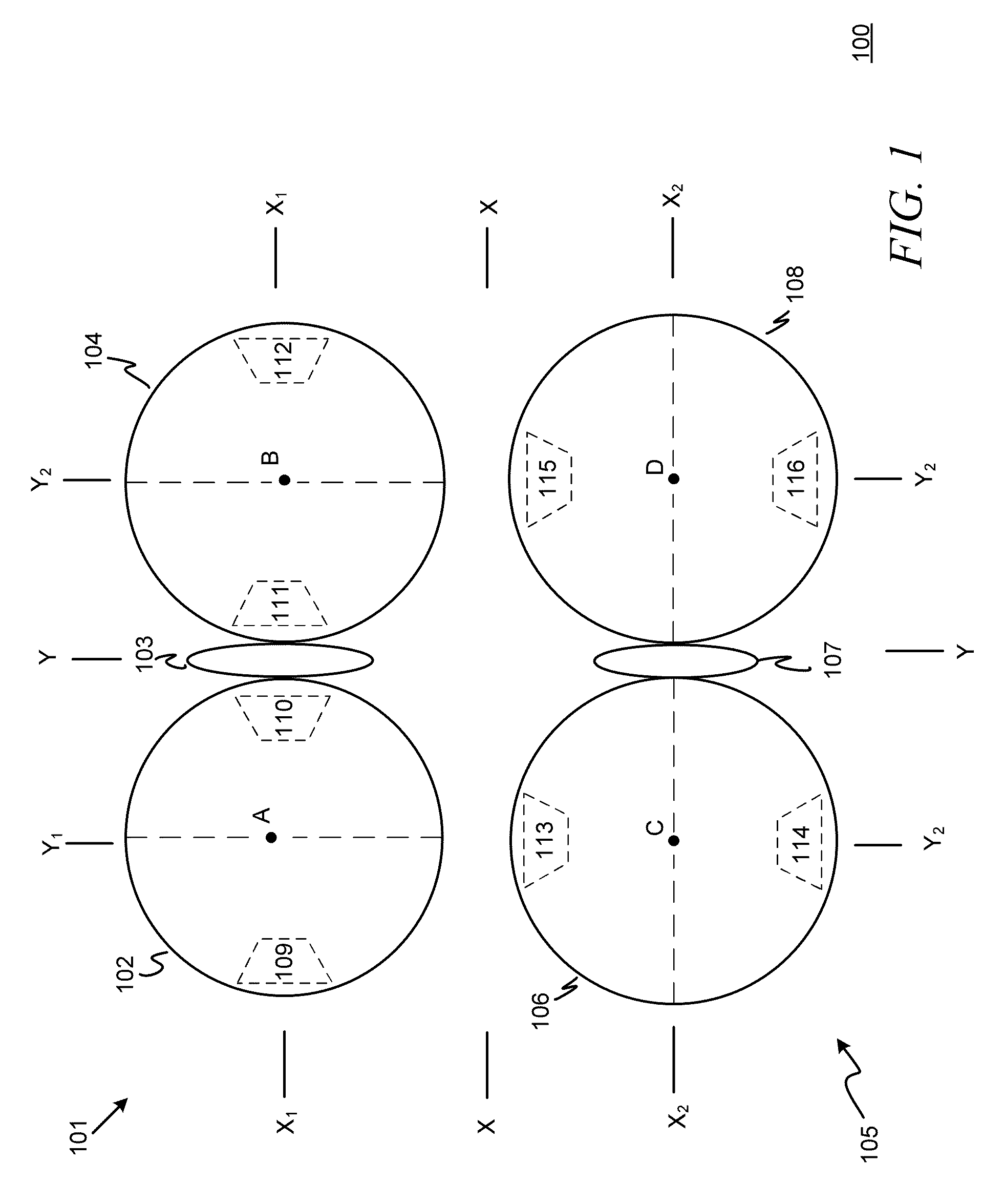
[0024]In exemplary embodiments of the present invention, an X-Y axis gyroscope incorporates two specially-configured single-axis gyroscopes to sense rotations about two orthogonal axes (the axes of sensitivity) in the device plane. Each single-axis gyroscope includes a resonator having two rotationally-dithered shuttles interconnected by a coupling (referred to hereinafter for convenience as a “fork”), where each shuttle is configured to tilt out-of-plane along a tilt axis perpendicular to the axis of sensitivity and includes corresponding Coriolis sensing electrodes positioned along an axis perpendicular to the tilt axis (i.e., parallel to the axis of sensitivity). Among other things, such a configuration tends to reduce sensitivity of each single-axis gyroscope to out-of-p...


PUM


Abstract

Inertial sensors with reduced sensitivity to quadrature errors and micromachining inaccuracies include a gyroscope incorporating two specially-configured single-axis gyroscopes for sensing rotations about two orthogonal axes (the axes of sensitivity) in the device plane, where each single-axis gyroscope includes a resonator having two rotationally-dithered shuttles interconnected by a fork and each shuttle is configured to tilt out-of-plane along a tilt axis perpendicular to the axis of sensitivity and includes corresponding Coriolis sensing electrodes positioned along an axis perpendicular to the tilt axis (i.e., parallel to the axis of sensitivity). The two single-axis gyroscopes may be interconnected, e.g., by one or more in-phase or anti-phase couplings interconnecting the forks and / or the shuttles.

Description

FIELD OF THE INVENTION[0001]The present invention relates to micromachined inertial sensors, and more particularly to inertial sensors with reduced sensitivity to quadrature errors and micromachining inaccuracies such as sidewall angle asymmetry of the flexures used to support resonator shuttles.BACKGROUND OF THE INVENTION[0002]Micromachined (MEMS) gyroscopes have become established as useful commercial items. Generally speaking, a MEMS gyroscope incorporates two high-performing MEMS devices, specifically a self-tuned resonator in the drive axis and a micro-acceleration sensor in the sensing axis. Gyroscope performance is very sensitive to such things as manufacturing variations, errors in packaging, driving, linear acceleration, and temperature, among other things. Basic principles of operation of angular-rate sensing gyroscopes are well understood and described in the prior art (e.g., Geen, J. et al., New iMEMS Angular-Rate-Sensing Gyroscope, Analog Devices, Inc., Analog Dialog 37...

Claims


Application Information

Patent Timeline
Patent Type & Authority Applications(United States)
IPC IPC(8): G01C19/56
CPCG01C19/5712
Inventor KUANG, JINBOGEEN, JOHN A.
Owner ANALOG DEVICES INC
Learn More