

Fluid circulation arrangement for providing an intensified wash effect in a dishwasher and an associated method
- Summary
- Abstract
- Description
- Claims
- Application Information
AI Technical Summary
Benefits of technology
Problems solved by technology
Method used
Image

Examples
first embodiment
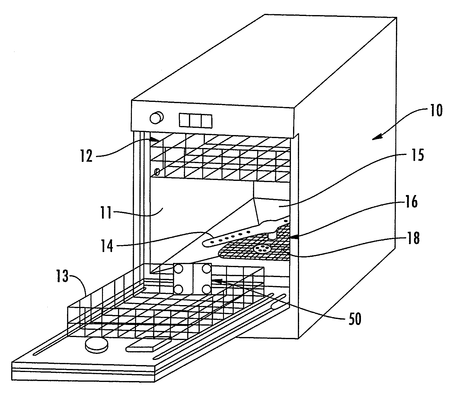
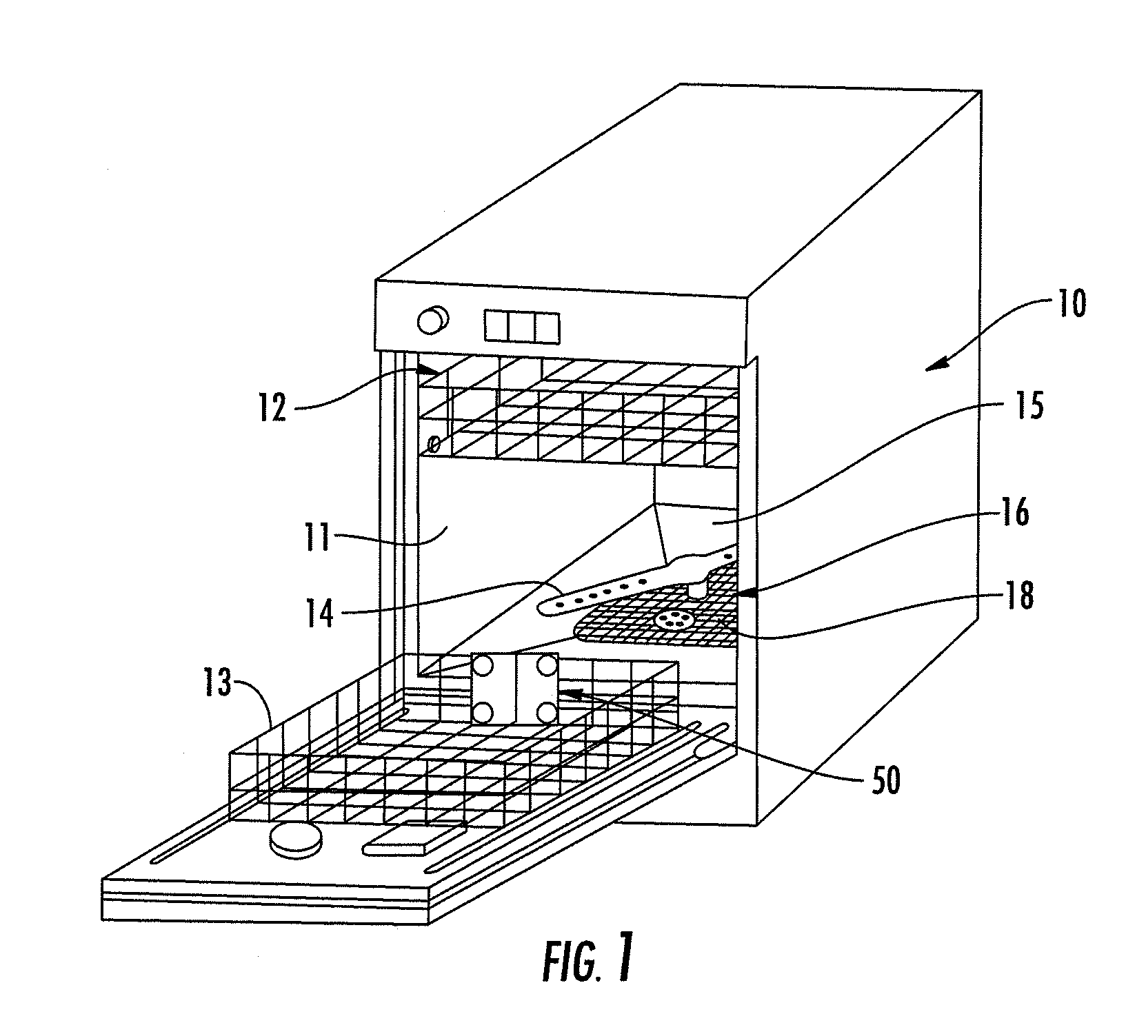
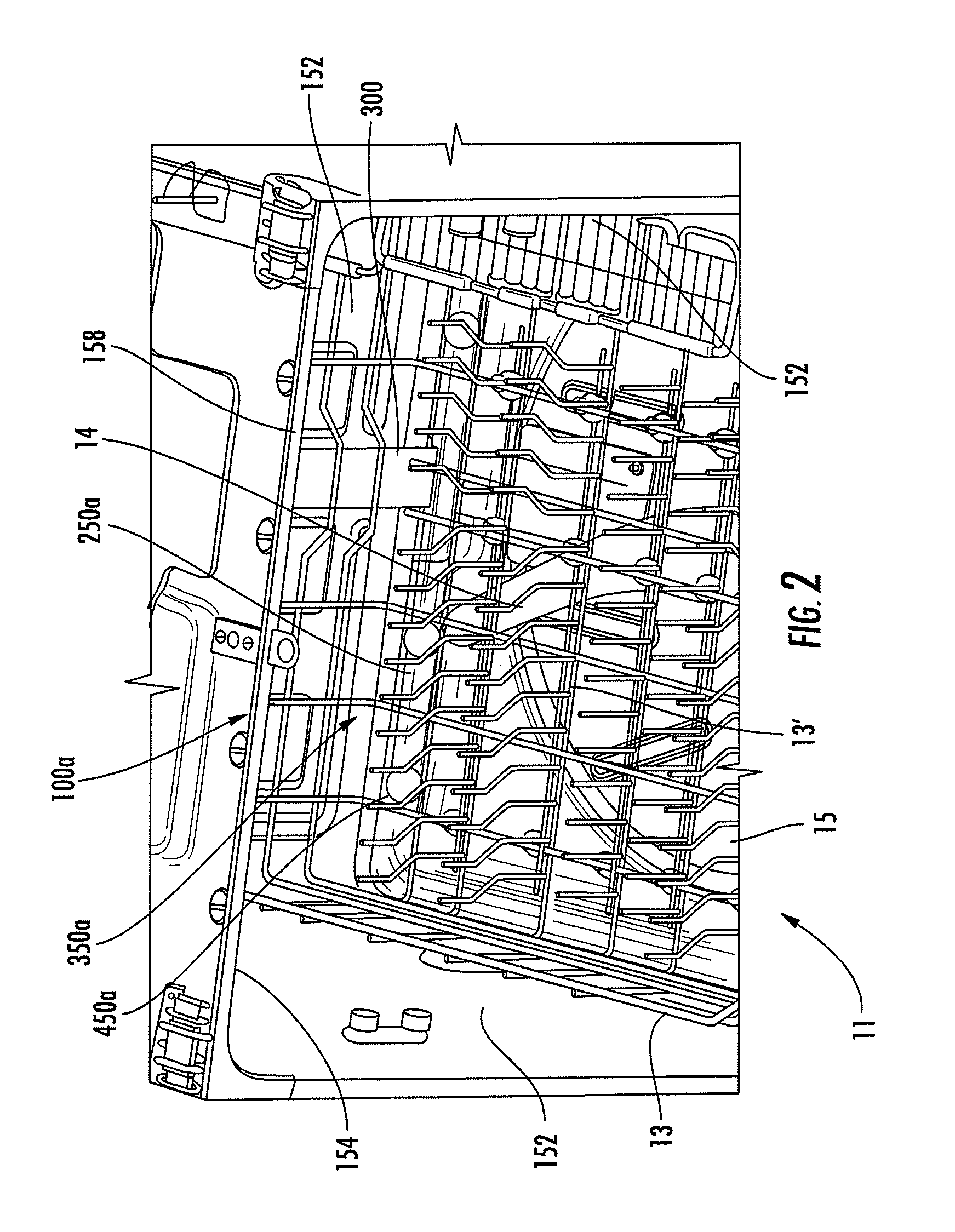
[0031]FIGS. 2-9 illustrate a fluid circulation arrangement for a dishwasher according to one aspect of the present invention, indicated generally by the numeral 100a. The fluid circulation arrangement 100a is configured to circulate dishwashing fluid within the tub portion 11 of the dishwasher, wherein the tub portion 11 generally includes a plurality of walls (e.g., sides 152, top 154 and bottom 15) cooperating to define a forward opening 158. Disposed within a lower end of the tub portion 11 is a rack 13 adapted to receive dishware therein. The rack 13 may comprise a bottom 13′ and one or more sidewalls 13″ which may be formed from interconnected horizontal and vertical wires. A dishwashing fluid supply conduit 250a may also be disposed about the lower end of the tub portion 11, wherein the dishwashing fluid supply conduit 250a may be further configured to extend laterally across the lower end of the tub portion 11, adjacent to the bottom wall and / or one of the side walls thereof....
third embodiment
[0051]However, particular embodiments of arms and other features which may be associated with various embodiments of the fluid circulation arrangement will now be discussed. In this regard, FIGS. 21-23 illustrate a fluid circulation arrangement 100c comprising an arm 500c. In the illustrated embodiment the spray assembly 350c is coupled to the rack 13 so as to be supported thereby. For example, the spray assembly 350c may be coupled to the sidewall 13″ and / or the bottom 13′ of the rack 13. In this regard, a base member 358c of the spray assembly 350c may be coupled to the rack 13, for example using the above-described attachment assemblies. The fluid circulation arrangement 100c may include a fluid connector such as the releasable fluid connector described above. In this regard a releasable first connector 356c′ is illustrated extending from the base member 358c in FIG. 23 which may engage a second connector coupled to a dishwashing fluid supply channel to provide fluid communicatio...
fourth embodiment
[0053]Various other embodiments of arms which may be used in fluid circulation arrangements are illustrated in FIGS. 24-30. The arms may comprise many of the features described above, and hence not all features of the arms will be described in detail for purposes of brevity. For example, FIGS. 24A-B illustrate a fluid circulation arrangement 100d. In this embodiment the arm 500d may be configured to rotate about an axis 506d whereby the arm 500d and nozzle head 450d remain adjacent to the bottom 13′ of the rack 13. Further, the arm 500d may comprise an extensible section 508d which is configured to extend or retract the length of the arm 500d. Thereby, as illustrated in FIG. 24B, the arm 500d may position the nozzle head 450d and thus the nozzle member 400d in a variety of positions within an intensified wash area 510d to provide an intensified wash effect at a desired location. Further, when an intensified wash effect is not needed, the arm 500d may be positioned proximate the side...
PUM
 Abstract
Description
Claims
Application Information