Device for blowing gas onto a face of traveling strip material

a technology of traveling strip and gas, which is applied in the direction of heat treatment apparatus, drying machines with progressive movement, furnaces, etc., can solve the problems of affecting the stability of the strip, affecting the production capacity of the strip, and inability to solve the problem of the free margin zone of the traveling strip in any way, so as to improve the production capacity and increase the travel speed of the strip

Active Publication Date: 2011-02-10
COCKERILL MAINTENANCE & INGIE
View PDF5 Cites 12 Cited by
  • Summary
  • Abstract
  • Description
  • Claims
  • Application Information

AI Technical Summary

Benefits of technology

[0026]Thus, the movable shutter member may be moved freely as a function of needs, and in particular as a function of strips having different widths.
[0027]Indeed in this respect, it should be observed that the widths of strips generally lie in the range 400 mm to 2200 mm, but that only 30% to 40% of a year's worth of orders relates to strips of maximum width. Consequently, since the flow rate that is genuinely required is less for narrower strip widths, the fact of retaining the same flow rate with a narrower strip makes it possible to increase the travel speed of the strip, thereby further improving production capacities.

Problems solved by technology

The various documents mentioned above seeking to improve temperature uniformity of the strip in a transverse direction are of interest, but without in any way solving the problems that arise in the zone of the free margins of the traveling strip.
These problems are both thermal, insofar as edge effects make it difficult to obtain uniform temperature, and also aerodynamic, insofar as the jets of gas blown from the two boxes disposed on either side of the traveling strip create turbulence that disturbs both the stability of the strip and the uniformity of the atmosphere in the vicinity of the free margins of said traveling strip.
The above-mentioned problems become more complicated when there are changes in strip format, in particular in strip width.
Thus, if it is desired to preserve good uniformity of cooling, it is necessary to ensure that the blow width is always excessive, and consequently it is necessary to run at a flow rate that is abnormally high compared with the genuine requirements for blowing gas.

Method used


Image

  • Device for blowing gas onto a face of traveling strip material
  • Device for blowing gas onto a face of traveling strip material
  • Device for blowing gas onto a face of traveling strip material

Examples


Embodiment Construction

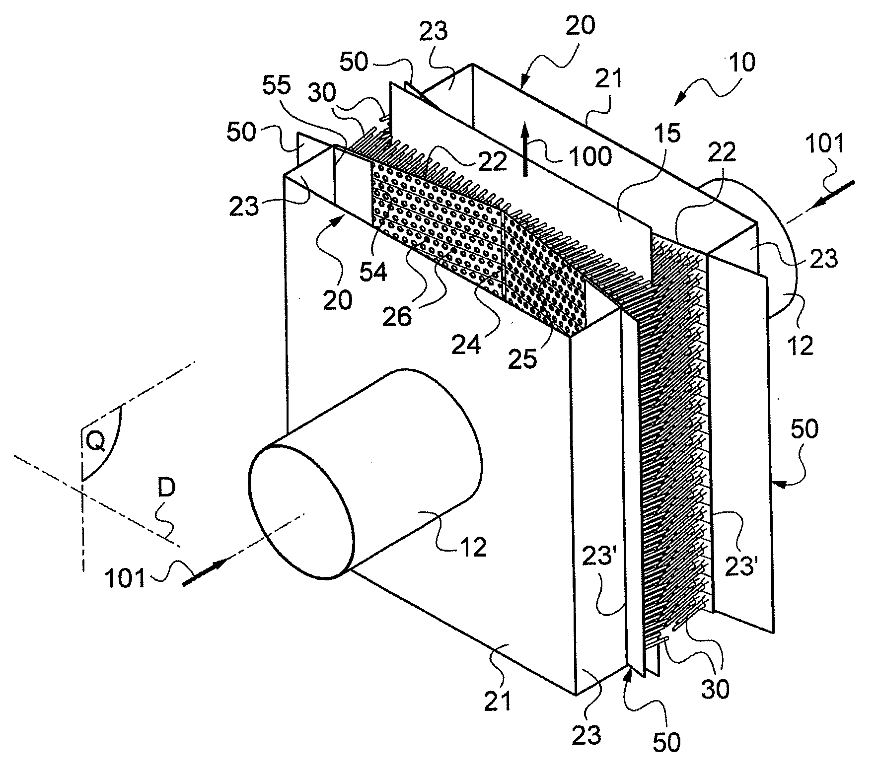
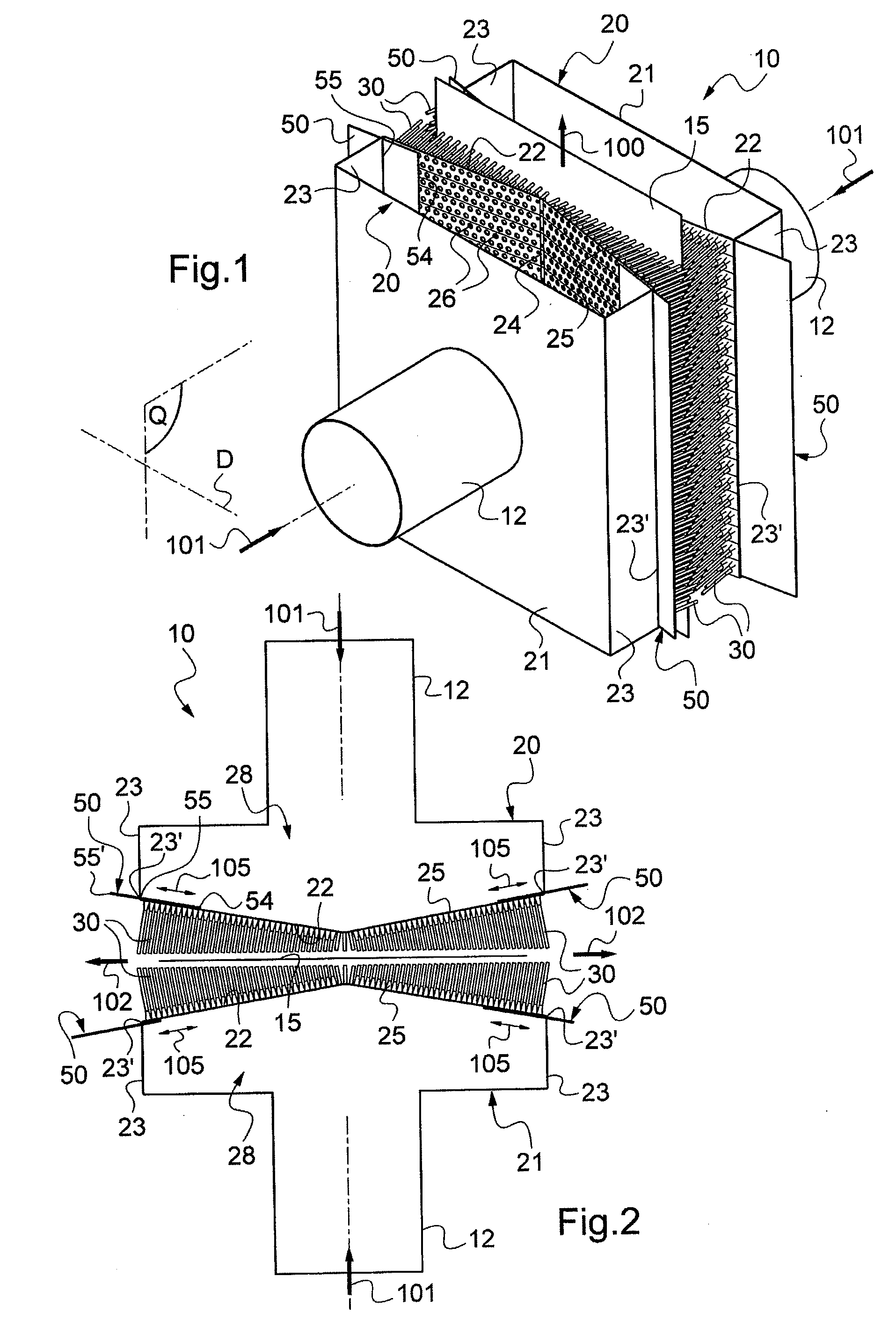
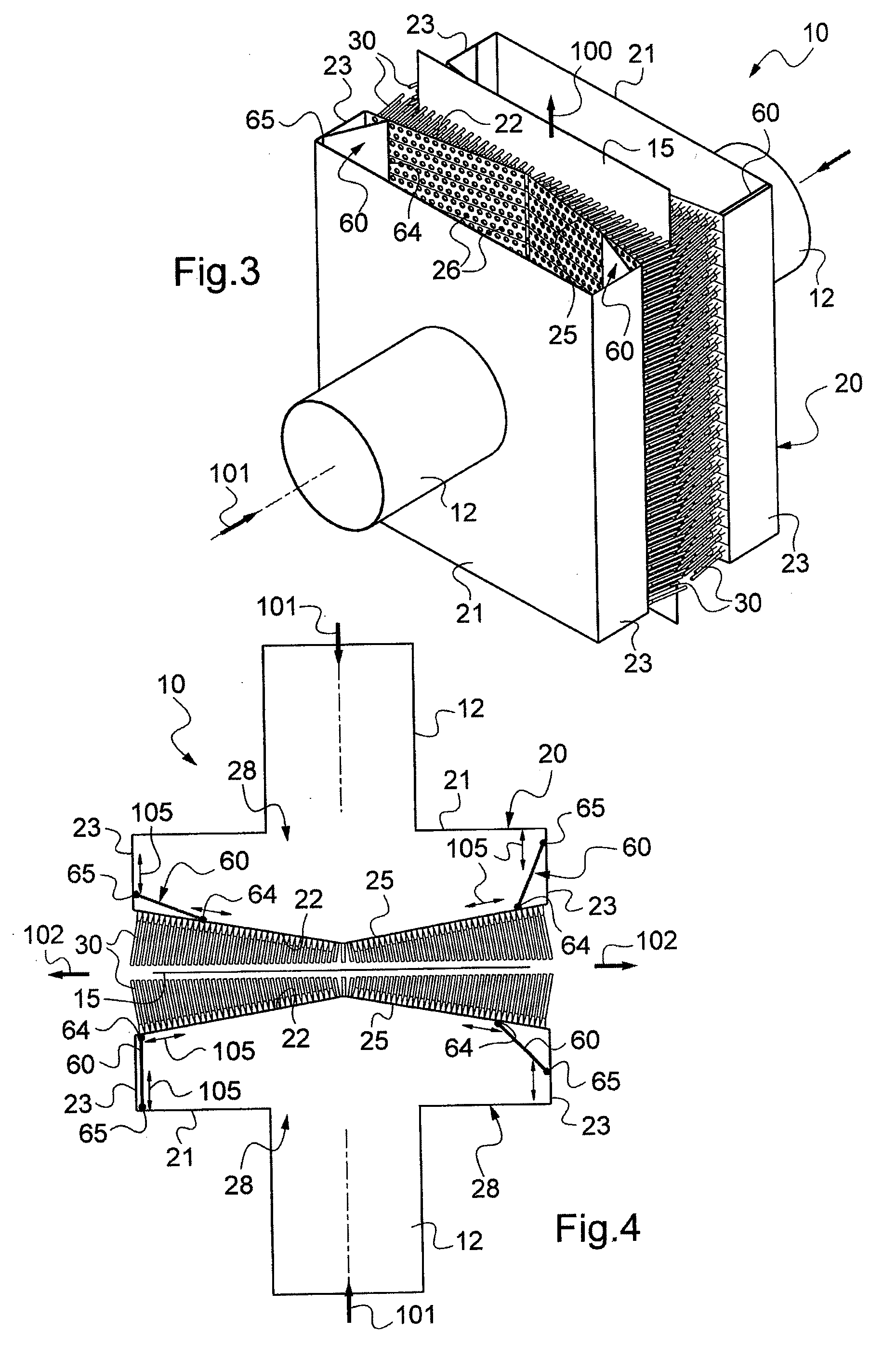
[0046]FIGS. 1 and 2 show a portion of a blow installation including a gas blow device in accordance with the invention given overall reference 10.

[0047]On either side of traveling strip material referenced 15, the travel direction being symbolized by an arrow 100, the device 10 comprises a respective hollow box 20 with the strip material 15 traveling between the two facing boxes 20.

[0048]Each hollow box 20, of inside space referenced 28, comprises a rear wall 21 to which a blowing gas admission tube 12 is connected, the blow gas feed being symbolized by an arrow 101, a front or active wall 22 opposite from the wall 21, and facing towards the corresponding face of the strip material 15, together with two side walls 23.

[0049]The wall 22 of each hollow box is fitted with a plurality of blow orifices serving to direct the gas towards the corresponding face of the strip material 15. Specifically, the blow orifices are constituted by tubular nozzles 30 projecting at least in part from the...


PUM

PropertyMeasurementUnit
widthaaaaaaaaaa
widthaaaaaaaaaa
movementaaaaaaaaaa

Abstract

A device for blowing gas on a face of traveling strip material, comprising at least one hollow box having its wall fitted with a plurality of blow orifices, thereby enabling gas to be directed towards said face of the strip material. The hollow box is also fitted laterally on at least one side thereof relative to a midplane (Q) perpendicular to the plane in the strip with a movable shutter member having the function of selectively shutting some of the blow orifices. In order to adapt the width of the blow zone to the width of the corresponding strip material, said movable shutter member has an edge adjacent to the inside surface of the wall fitted with the blow orifices, and an edge adjacent to a side wall of the hollow box.

Description

[0001]The present invention relates to a device for blowing gas on a surface of traveling strip material.[0002]The invention relates most particularly to lines for processing steel or aluminum strip making use of at least one chamber for cooling by means of gas jets, or a section for cooling by means of gas jets, such as heat treatment lines, in particular lines for performing continuous annealing, or such as coating lines, in particular galvanizating lines. The treatment lines concerned may equally well require gas to be blown in order to preheat strips, as occurs for chromating treatment with metal strips being annealed, during which a protective varnish is deposited and dried by blowing hot air.[0003]Nevertheless, the invention is not limited to the above-specified field of use, and it relates more generally to blowing gas onto a surface of traveling strip material that need not necessarily be a metal material, e.g. it could be paper or plastics material, in order to perform dryi...

Claims


Application Information

Patent Timeline
Patent Type & Authority Applications(United States)
IPC IPC(8): F03B13/00
CPCB21B45/004B21B45/0209C21D1/613C21D1/667F15D1/00C21D9/5735C21D9/63F26B13/007F26B13/108C21D9/46Y10T137/8593Y10T137/8376
Inventor LANGEVIN, STEPHANEDUBOIS, PATRICK
Owner COCKERILL MAINTENANCE & INGIE
Why Eureka
Try Eureka