Glare detection and mitigation method for a photo-sensitive display device

a display device and glare detection technology, applied in static indicating devices, cathode-ray tube indicators, instruments, etc., can solve the problems of image washout and other problems, and achieve the effects of reducing the number of glare detections, and increasing display brightness

Inactive Publication Date: 2011-02-10
DELPHI TECH INC
View PDF13 Cites 15 Cited by
  • Summary
  • Abstract
  • Description
  • Claims
  • Application Information

AI Technical Summary

Benefits of technology

[0003]The present invention is directed to a novel method of operation for a display device with integral photo-sensors that detects veiling glare and mitigates the effects of the detected glare. The photo-sensors are periodically sampled to identify optically saturated regions of the display. If the saturated regions of the display are being used to convey relevant information, one or more counter-measures are initiated to mitigate the effects of the glare. The counter-measures may include: increasing the display brightness at least in the identified glare region, tilting the display or its cover lens away from an estimated direction of the glare source, re-sizing or re-formatting the displayed information, using an alternate display device or communication medium to convey the information, and presenting the information with a different layer of a multi-layer display.

Problems solved by technology

In spite of the advantages such display devices offer, they still suffer from image wash-out due to veiling glare when used in a high ambient lighting environment such as in the console or instrument cluster of a motor vehicle.

Method used


Image

  • Glare detection and mitigation method for a photo-sensitive display device
  • Glare detection and mitigation method for a photo-sensitive display device
  • Glare detection and mitigation method for a photo-sensitive display device

Examples


Embodiment Construction

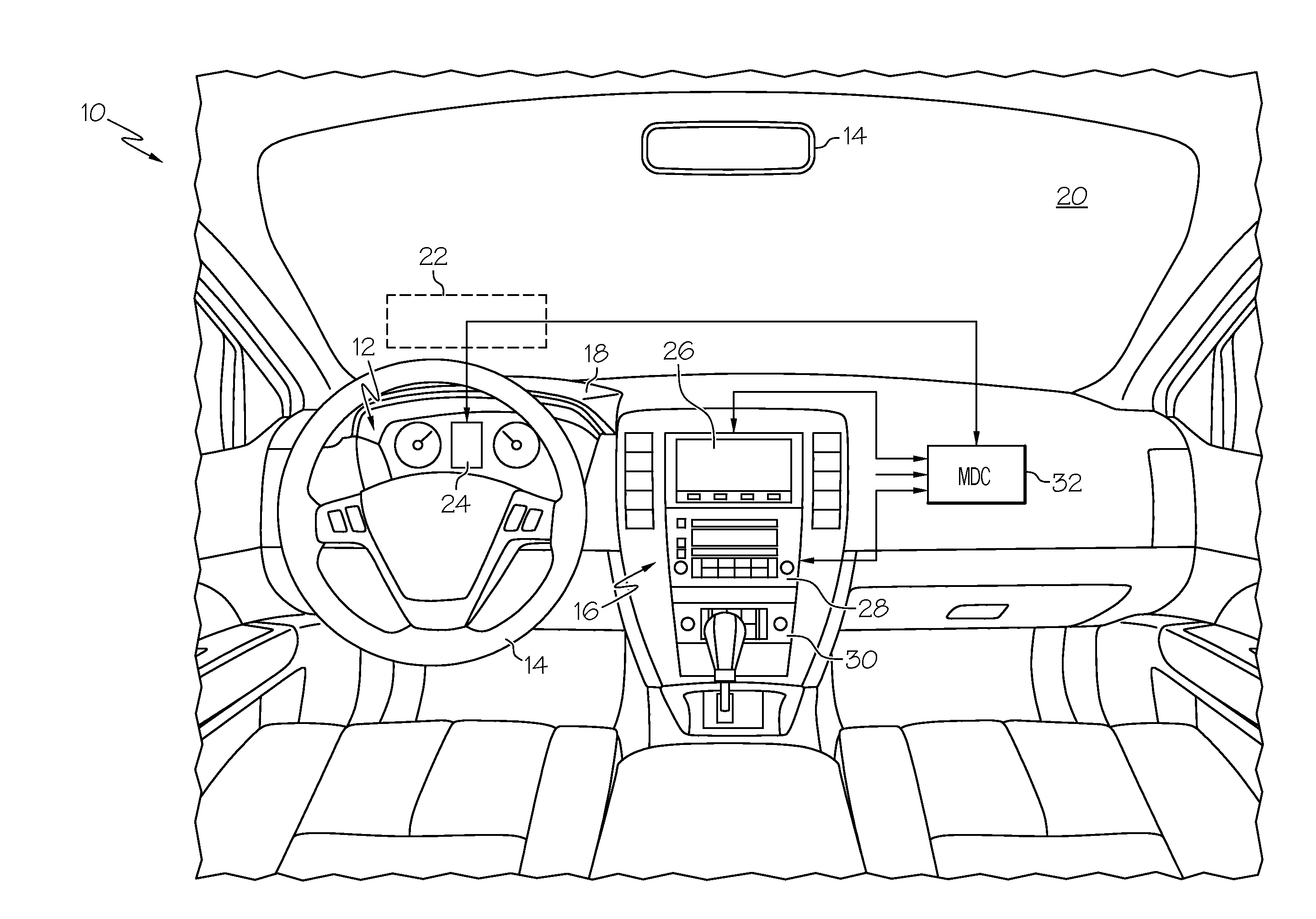
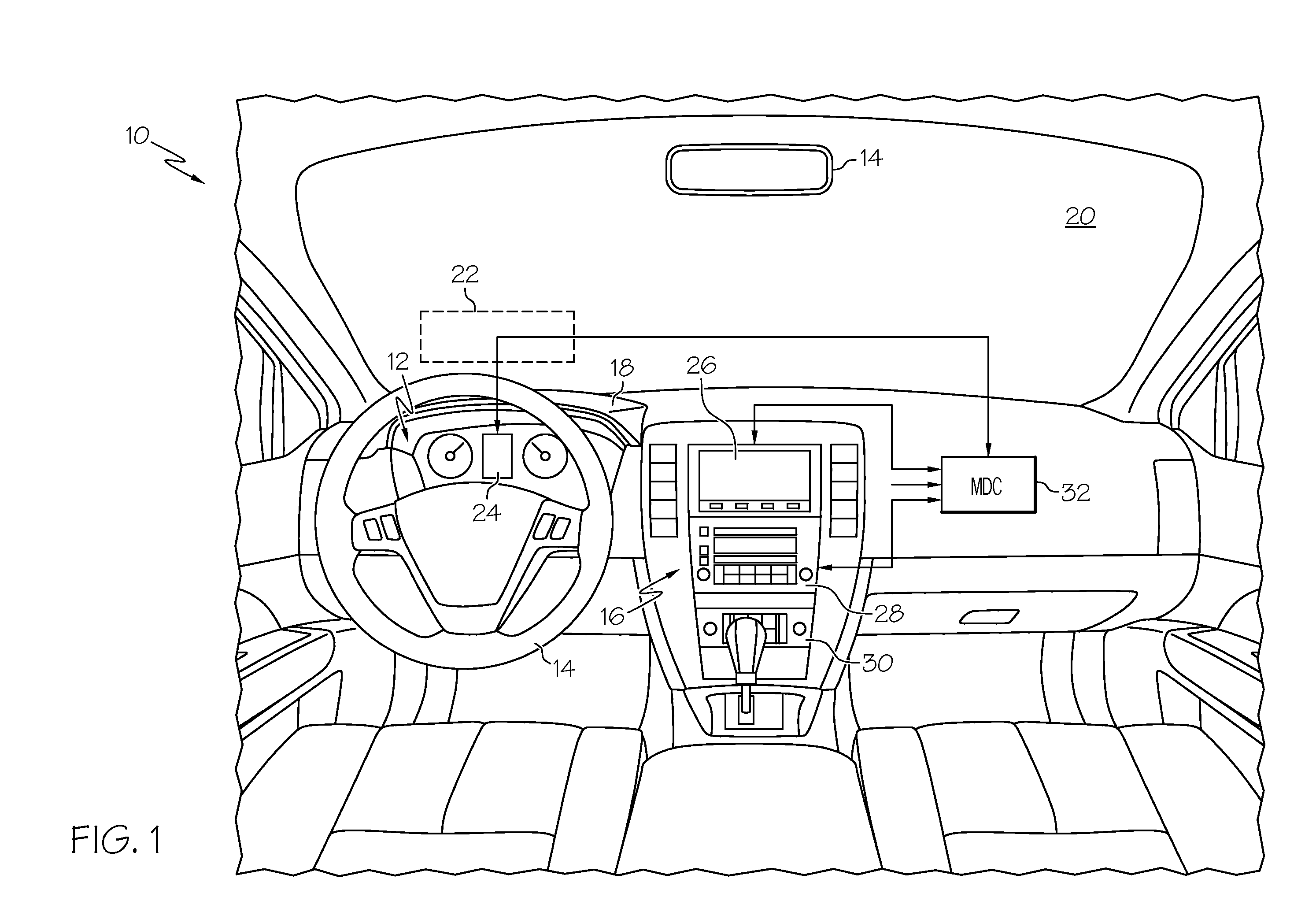
[0008]Referring to the drawings, and particularly to FIG. 1, the reference numeral 10 generally designates the front portion of a vehicle passenger compartment. Display devices are ordinarily installed in an instrument cluster 12 forward of the steering wheel 14, or in a center console 16, although a head-up display unit (not shown) mounted on the instrument panel 18 under the windshield 20 can also be used to project information from a display device onto a lower region 22 of windshield 20. In the illustrated embodiment, a relatively small reconfigurable LCD display device 24 is mounted in the instrument cluster 12 for displaying vehicle status or system information, and a relatively large reconfigurable LCD display device 26 is mounted in the upper portion of center console 16 for displaying navigation maps and information. As is customary, an audio control panel 28 and an HVAC control panel 30 are mounted in the center console 16 below the display device 26.

[0009]The information ...


PUM


Abstract

A display device having integral photo-sensors for touch sensing is used to detect and mitigate the effects of veiling glare that obscures information being conveyed by the display device. The photo-sensors are periodically sampled to identify optically saturated regions of the display device. If the saturated regions of the display device are being used to convey relevant information, one or more counter-measures are initiated to mitigate the effects of the glare. The counter-measures may include: increasing the display brightness at least in the identified glare region, tilting the display or its cover lens away from estimated direction of the glare source, re-sizing or re-formatting the displayed information, using an alternate display device to convey the information, and presenting the information with a different layer of a multi-layer display.

Description

TECHNICAL FIELD[0001]The present invention relates to display devices including integral photo-sensors for touch sensing and / or imaging, and more particularly to a method of operation for detecting glare and mitigating its effects.BACKGROUND OF THE INVENTION[0002]Various manufacturers have introduced active-matrix thin-film transistor electro-chromic (LCD or OLED, e.g.) multi-touch screen displays, where photo-sensor elements integrated into the pixel matrix are used to optically detect user touch points. See, for example, the U.S. Pat. No. 5,172,104 issued to U.S. Philips Corporation on Dec. 15, 1992. The photo-sensor elements have also been used for imaging purposes, such as for scanning an object placed on the screen of the display device, or even imaging a user of the display device. In spite of the advantages such display devices offer, they still suffer from image wash-out due to veiling glare when used in a high ambient lighting environment such as in the console or instrumen...

Claims


Application Information

Patent Timeline
Patent Type & Authority Applications(United States)
IPC IPC(8): G09G5/02
CPCG09G3/20G09G2320/0633G09G2360/144G09G2340/0407G09G2320/066
Inventor HARBACH, ANDREW P.HAMMOUD, RIAD I.
Owner DELPHI TECH INC
Why Eureka
Try Eureka