

Membrane, especially for an optical device having a deformable membrane
a technology of optical devices and membranes, applied in the field of membranes, can solve the problems of bulky and complex type of actuation, far too high cost for this kind of application, and complicated mechanical structures associated with membranes, and achieve the effect of reducing the cost of operation
- Summary
- Abstract
- Description
- Claims
- Application Information
AI Technical Summary
Benefits of technology
Problems solved by technology
Method used
Image

Examples
Embodiment Construction
The present invention has precisely the aim of providing an optical device with deformable membrane such as a liquid lens or a mirror that does not have the above mentioned drawbacks, namely the complexity of the actuating means and their size, optical aberrations, the high risk of leakage, the incompatibility with the micro-electronic environment, the impossibility of a collective manufacture according to the standards used in microelectronics.
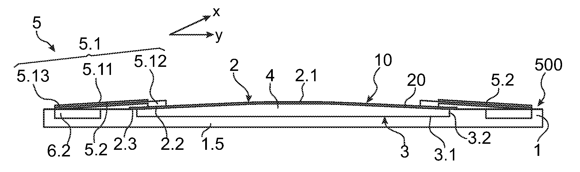
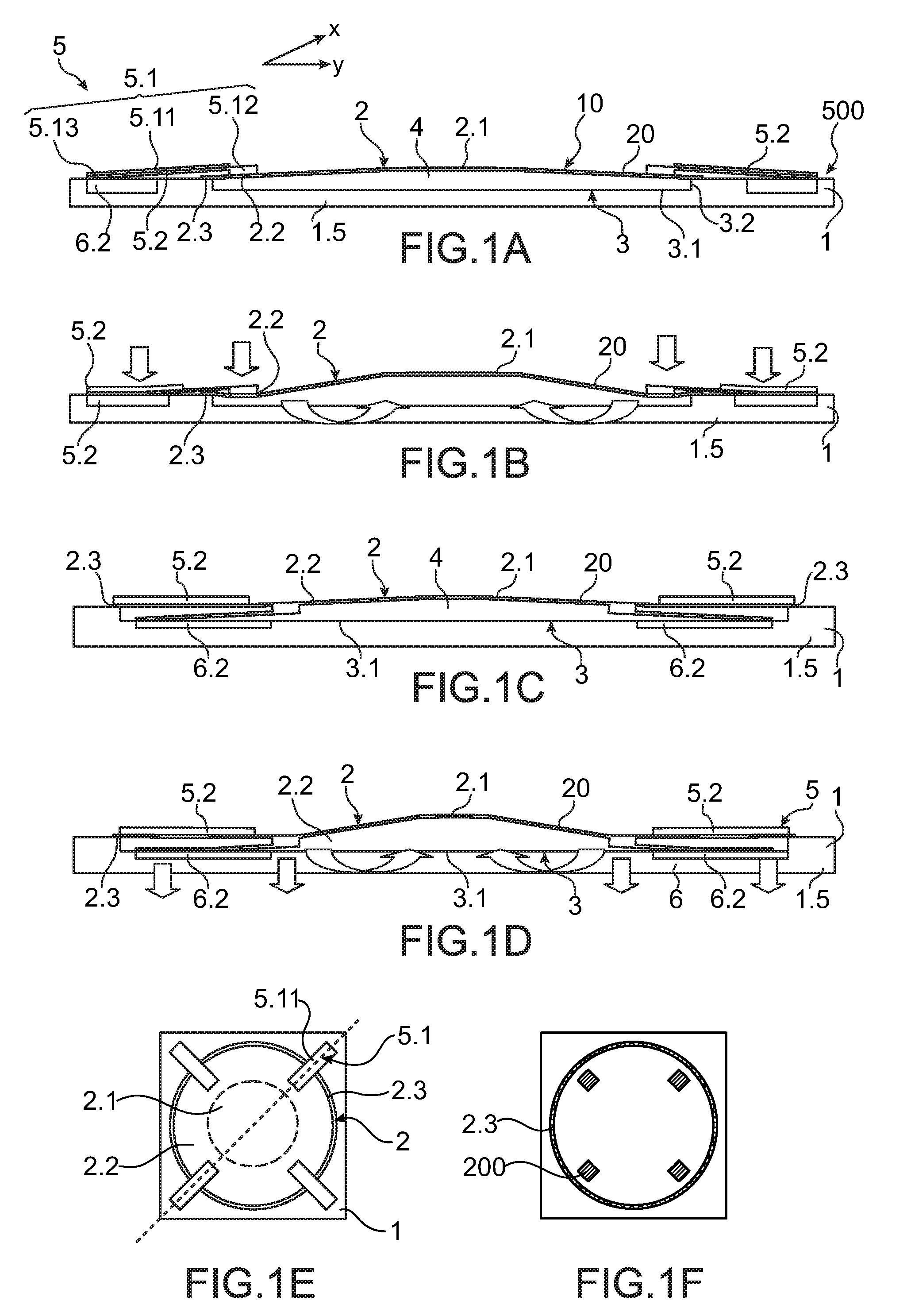
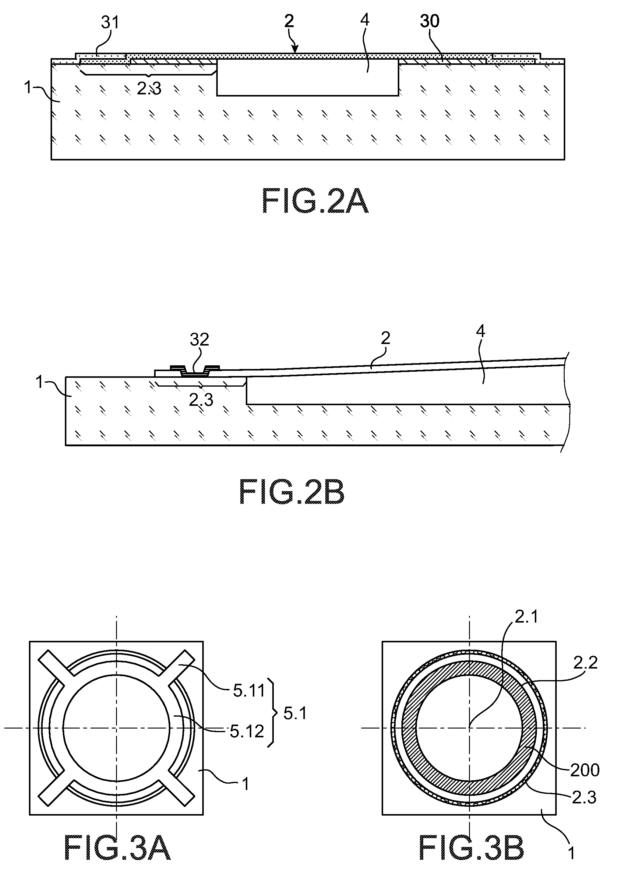
To achieve this aim, the present invention proposes an optical device comprising a membrane deformable in a reversible manner comprising a flexible film having at least one peripheral anchoring zone, a central zone, an intermediate zone between the central zone and the peripheral anchoring zone. The membrane is anchored at the level of its anchoring zone on a support. It comprises in addition electrostatic actuating means with one or more fixed electrodes borne by the support and one or more movable parts. The support and the membrane contrib...
PUM
| Property | Measurement | Unit |
|---|---|---|
| refractive index | aaaaa | aaaaa |
| Young's modulus | aaaaa | aaaaa |
| thickness | aaaaa | aaaaa |
Abstract
Description
Claims
Application Information