Zoom lens barrel that attains a higher photographing magnification

a zoom lens and magnification technology, applied in the field of zoom lens barrels, to achieve the effect of reducing spacing and high photographing magnification

Inactive Publication Date: 2011-02-10
CANON KK
View PDF5 Cites 17 Cited by
  • Summary
  • Abstract
  • Description
  • Claims
  • Application Information

AI Technical Summary

Benefits of technology

[0014]The present invention provides a zoom lens barrel which is capable of attaining a higher photographing...

Problems solved by technology

However, in the telephoto state (FIG. 3) where the spacing in the optical axis direction between the first lens group (1) and the second lens g...

Method used


Image

  • Zoom lens barrel that attains a higher photographing magnification
  • Zoom lens barrel that attains a higher photographing magnification
  • Zoom lens barrel that attains a higher photographing magnification

Examples


first embodiment

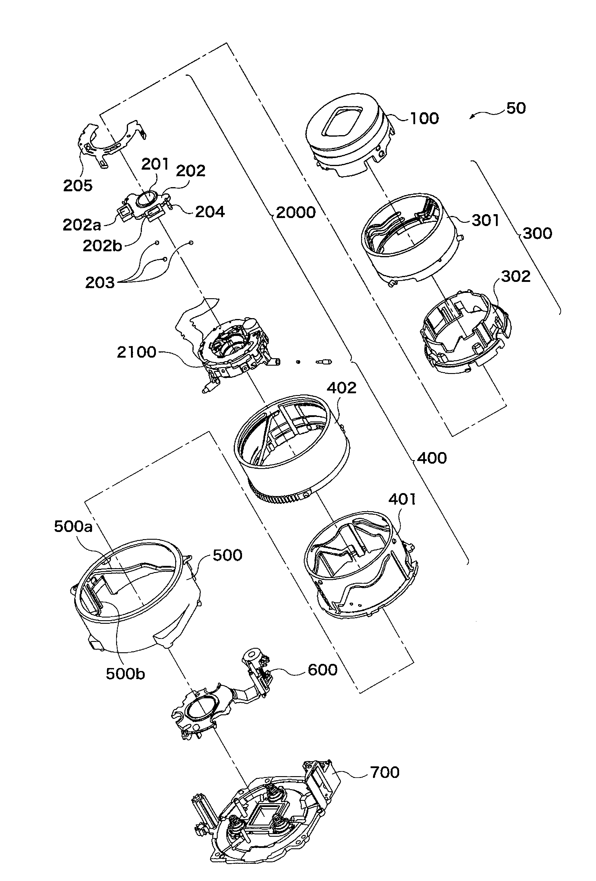
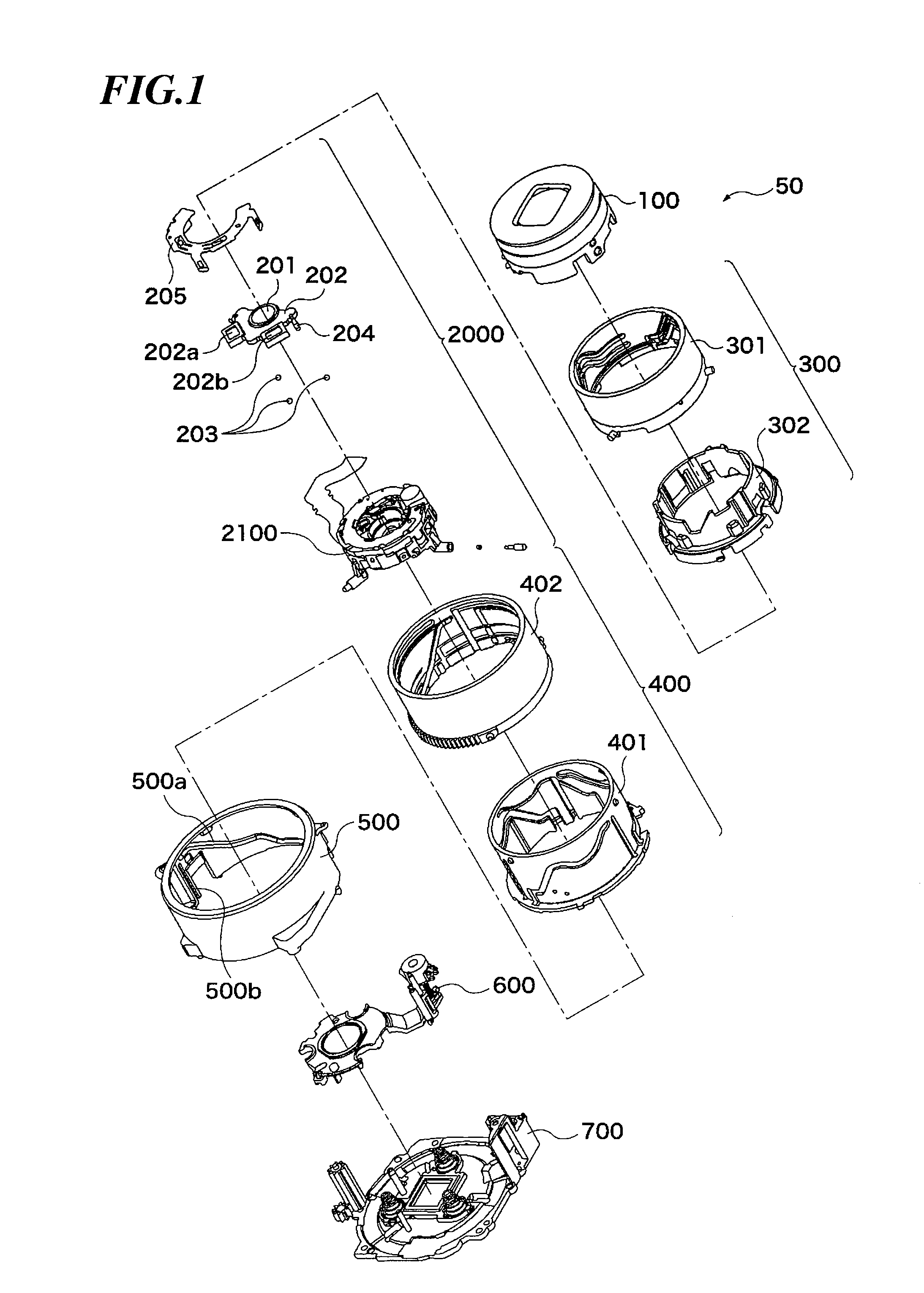
[0049]FIG. 1 is an exploded perspective view of the zoom lens barrel 50 according to the present invention. The zoom lens barrel 50 basically comprises a first group unit 100, a first movable cam unit 300, a second group unit 2000, a second movable cam unit 400, a fixed barrel 500, a third group unit 600, and a base unit 700. The second group unit 2000 includes an aperture shutter unit 2100.

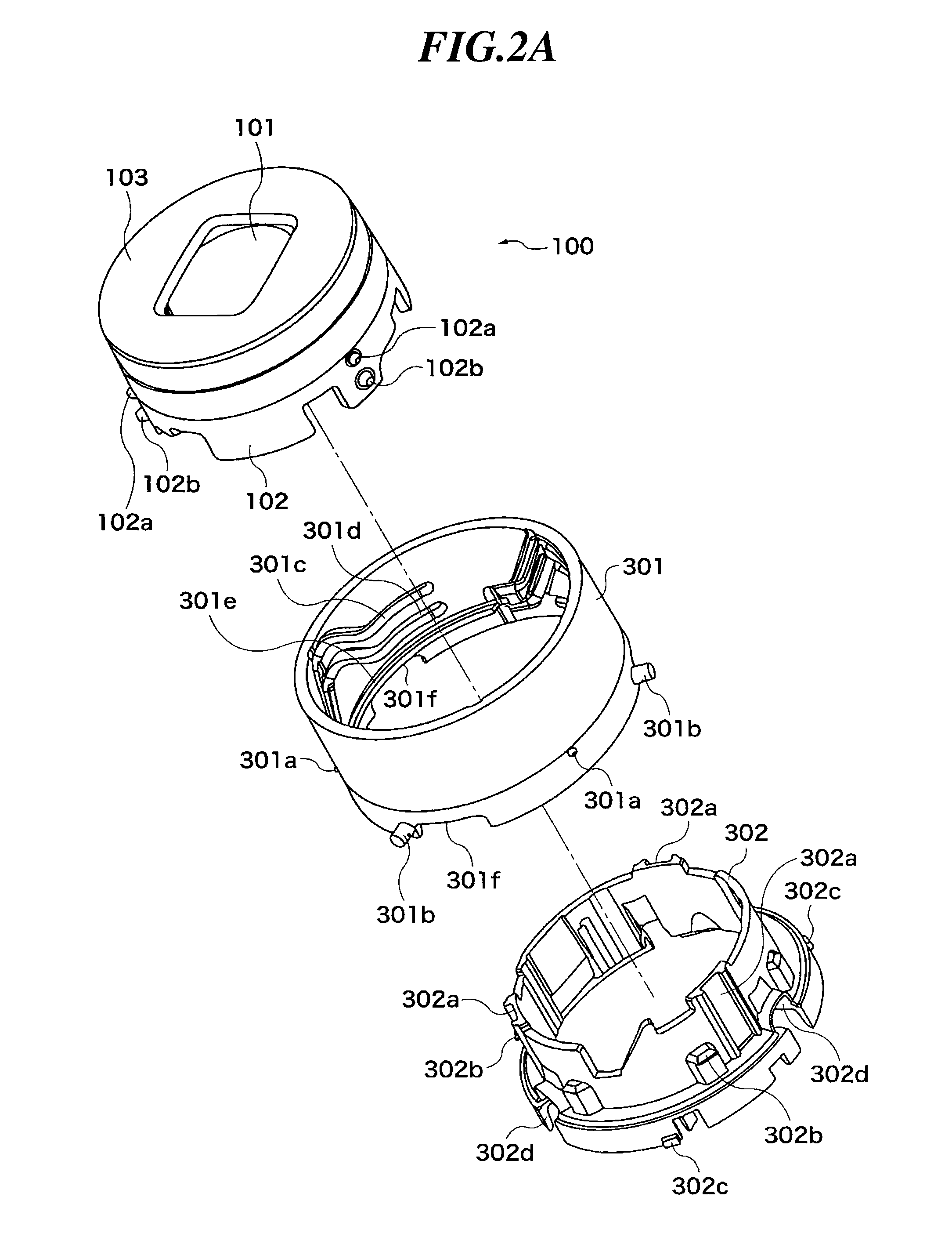
[0050]FIG. 2A is an exploded perspective view of the first group unit 100 and the first movable cam unit 300. The first movable cam unit is formed by a first cam barrel 301 and a rectilinear motion barrel 302. FIG. 2B is an exploded perspective view of the first group unit 100 and the first movable cam unit 300, as viewed from a different direction from a view direction in FIG. 2A.

[0051]The first group unit 100 comprises a first lens group 101, a first group barrel 102 (first hollow cylindrical unit) for holding the first lens group 101, and a cover member 103 attached to the first group barrel 1...

second embodiment

[0143]As described above, in the zoom lens barrel of the second embodiment, the urging force of the spring member 606 of the third group unit 800 and the driving force of the third lens group-holding member 801 are made use of in place of the resilient force of the spring member 702. This makes it possible to more reliably bring each of the follower parts 2101a and the movable follower part 2103a into contact with the one cam surface of the associated one of the cam grooves 402c and 402d.

[0144]Therefore, similarly to the first embodiment, it is possible to bring the zoom lens barrel into the retracted state by providing each of the cam grooves 402c and 402d with only one cam surface, which makes it possible to reduce the length of the third cam barrel 402 in the optical axis direction.

[0145]It is to be understood that the present invention is not limited to the above-described preferred embodiments, but it can be practiced in various forms without departing from the spirit and scop...


PUM


Abstract

A zoom lens barrel capable of attaining a higher photographing magnification by reducing spacing between lens groups in a telephoto state. A first lens group barrel holds a first lens group. A second lens group holding member supported by a third cam barrel holds a second lens group. A spring member urges the holding member toward the first lens group. Cam followers are formed at an opposite end of the holding member from the first lens group. Cam grooves for engagement with the cam followers are formed on the third cam barrel. When the holding member is urged by the spring member in a non-shooting region, each cam groove is brought into contact via one cam surface with the associated cam follower. In a shooting region, the cam groove is brought into contact with the cam follower via two cam surfaces.

Description

BACKGROUND OF THE INVENTION[0001]1. Field of the Invention[0002]The present invention relates to a zoom lens barrel having a plurality of stages of hollow cylindrical units that are extended in an optical axis direction.[0003]2. Description of the Related Art[0004]Conventionally, a lens barrel is configured such that in a wide-angle state, an object-side first lens group is largely extended in an optical axis direction to thereby increase spacing between the first lens group and a second lens group closer to an image-forming surface side than the first lens group is.[0005]Further, the lens barrel is configured such that when zooming is performed from a wide-angle position to a telephoto position, the second lens group is largely extended from the wide-angle position toward an object to thereby reduce the spacing between the first lens group and the second lens group.[0006]Furthermore, the lens barrel is configured such that in a non-shooting state, the first lens group and the secon...

Claims


Application Information

Patent Timeline
IPC IPC(8): G02B7/10
CPCG02B7/102
Inventor TSUJI, KANJI
Owner CANON KK
Why Eureka
Try Eureka