Determining method for use in information feedback, base station, user equipment, and communications system

a technology of information feedback and determining method, which is applied in the field of wireless transmission techniques, can solve the problems of increasing the load of wireless transmission, reducing the efficiency of frequency spectrum use for uplink, and consuming large amounts of data, so as to improve the quality of service of wireless cells, improve the accuracy of feedback, and reduce the amount of feedback information

Inactive Publication Date: 2011-02-10
SHARP KK
View PDF2 Cites 69 Cited by
  • Summary
  • Abstract
  • Description
  • Claims
  • Application Information

AI Technical Summary

Benefits of technology

[0030]The above methods and arrangements, which take into consideration the size of a subband set actually assigned to user equipment, make it possible to dynamically change the size and number of subbands for actual use in information feedback on the basis of the size of the subband set actually assigned to the user equipment. This im...

Problems solved by technology

A main challenge for the wireless telecommunications service, however, remains the same, i.e., how to offer a high-speed and high-performance service to as many pieces of user equipment (UE) as possible.
However, in a case where an amount of link information fed back from each piece of user equipment is excessively large, a total amount of feedback information constitutes extremely large volumes of data.
This further increases a load for wireless transmission in a feedback uplink, ...

Method used


Image

  • Determining method for use in information feedback, base station, user equipment, and communications system
  • Determining method for use in information feedback, base station, user equipment, and communications system
  • Determining method for use in information feedback, base station, user equipment, and communications system

Examples


application example 1

[0091](1) Configuration of a Wireless Cell

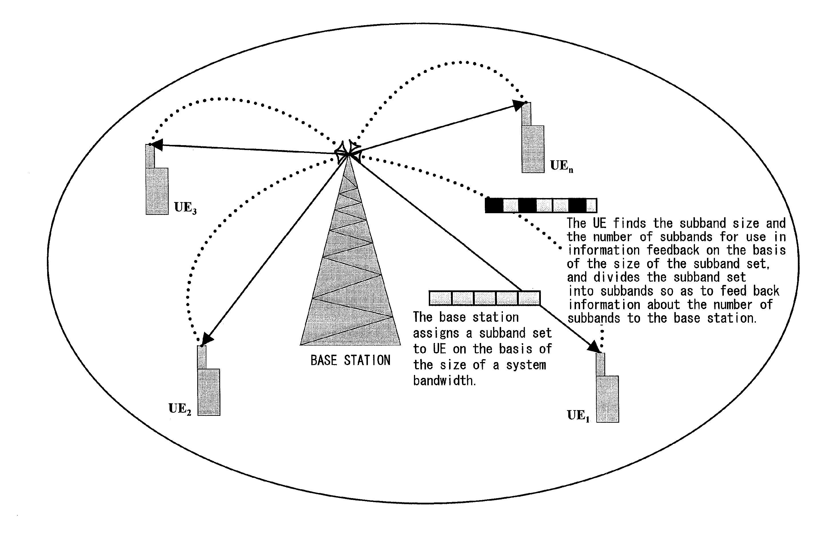
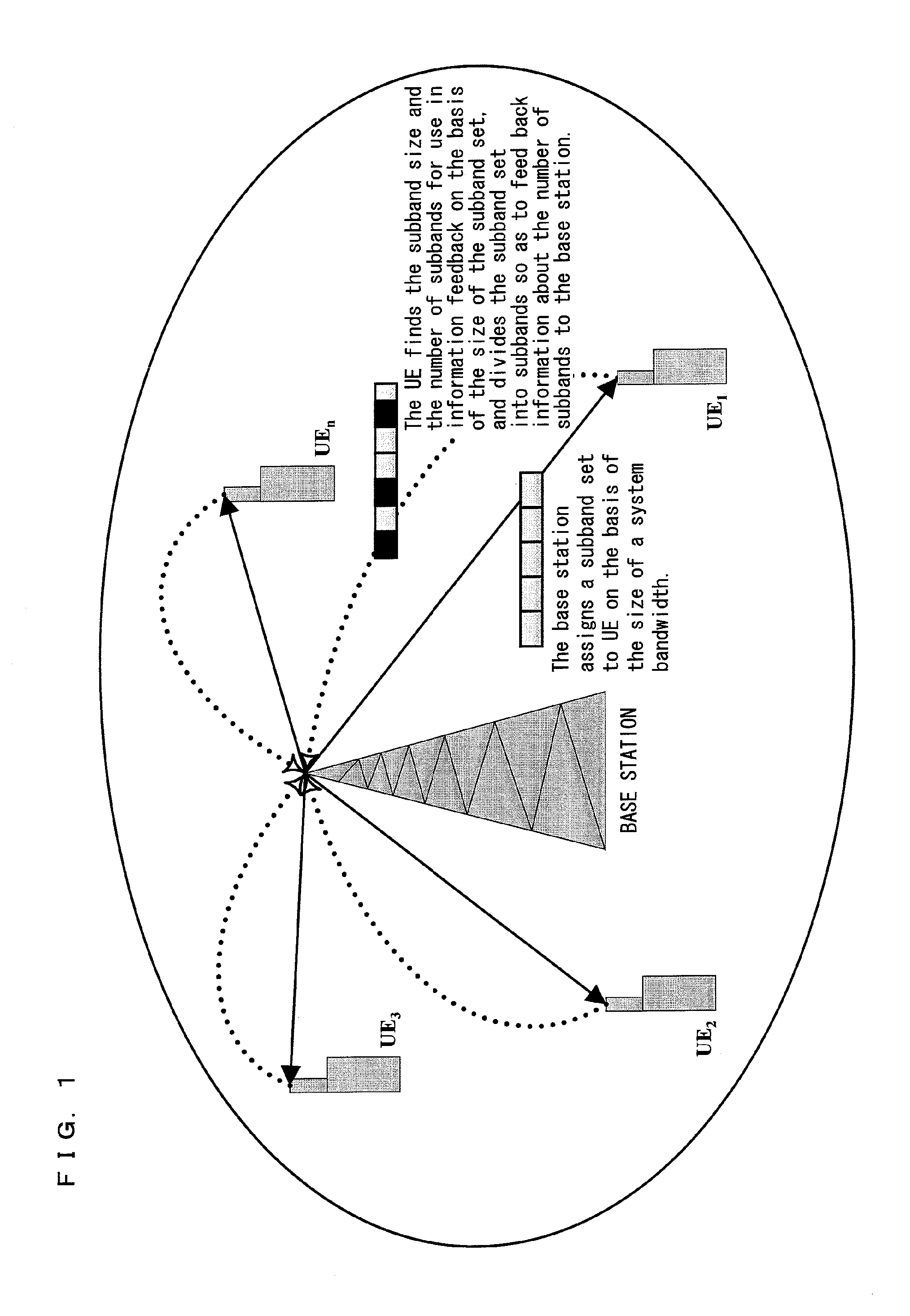
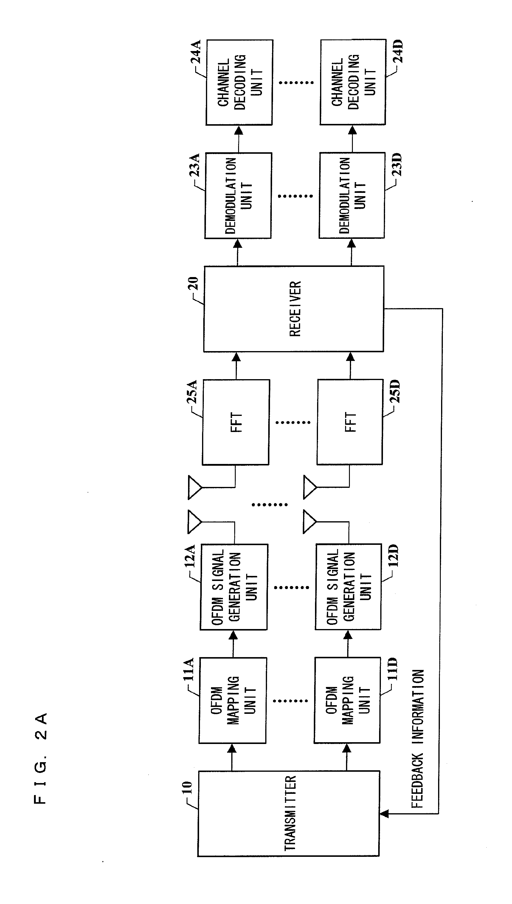
[0092]As illustrated in FIG. 1, a wireless cell includes a single base station (eNodeB) and plural pieces of user equipment (UE). FIGS. 2A through 2C illustrate the principle of how information is fed back within the wireless cell.

[0093](2) The subband division unit 13 of the base station obtains a subband size k (i.e., the number of resource blocks included in each subband) from Table 1, stored in a memory device (not shown) of the base station, on the basis of a system bandwidth size NSYS—RB (i.e., the number of resource blocks included in the system bandwidth). Refer to Table 1 below for a specific method of how the base station divides the system bandwidth into subbands. In Table 1, the size is expressed as the number of resource blocks (RBS).

TABLE 1SYSTEM BANDWIDTH SIZESUBBAND SIZENSYS—RB(RBS)k(RBS)6-7BROADBANDONLY 8-10211-26227-633 64-1104

[0094]Resource blocks in each subband are located continuously on a frequency spectrum. In a case ...

application example 2

[0103](1) Configuration of a Wireless Cell

[0104]As illustrated in FIG. 1, a wireless cell includes a single base station (eNodeB) and plural pieces of user equipment (UE). FIGS. 2A through 2C illustrate the principle of how information is fed back within the wireless cell.

[0105](2) The subband division unit 14 of the base station obtains a subband size k (i.e., the number of resource blocks included in each subband) from Table 1, stored in a memory device (not shown) of the base station, on the basis of a system bandwidth size NSYS—RB (i.e., the number of resource blocks included in the system bandwidth). Refer to Table 1 below for a specific method of how the base station divides the system bandwidth into subbands.

[0106]Resource blocks in each subband are located continuously on a frequency spectrum, and the individual subbands are sequentially located continuously on a frequency spectrum. In a case where a number PRB of resource blocks included in a continuous frequency spectrum p...

application example 3

[0115](1) Configuration of a Wireless Cell

[0116]As illustrated in FIG. 1, a wireless cell includes a single base station (eNodeB) and plural pieces of UE. FIGS. 2A through 2C illustrate the principle of how information is fed back within the wireless cell.

[0117](2) The subband division unit 14 of the base station finds a subband size k (i.e., a number of resource blocks included in each subband) on the basis of a system bandwidth size NSYS—RB (i.e., a number of resource blocks included in the system bandwidth). Refer to Table 1, stored in a memory device (not shown) of the base station, for a specific method of how the base station divides the system bandwidth into subbands.

[0118]Resource blocks in each subband are located continuously on a frequency spectrum, and the individual subbands are located continuously on a frequency spectrum in order of their respective numbers. In a case where a number PRB of resource blocks included in a continuous frequency spectrum part within the sys...


PUM


Abstract

The present invention provides a subband determining method, a base station, user equipment, and a communications system, each of which is used for information feedback. The base station of the present invention finds the subband size on the basis of a system bandwidth and divides the system bandwidth into subbands. The base station further (i) selects some subbands to form a subband set and assign the subband set to user equipment (UE) and (ii) notifies the user equipment (UE) of information about the subband set. The user equipment (UE) in turn finds its corresponding subband size and the number of subbands for use in feedback on the basis of the size of the assigned subband set. The user equipment (UE) further (i) divides the subband set into its corresponding subbands on the basis of a result found and (ii) feeds back information about a predetermined number of subbands to the base station. The base station carries out optimization of its transmitter on the basis of the information, fed back from the user equipment (UE), so as to not only secure a quality of service of a wireless cell, but also improve system efficiency. This method allows feedback to be carried out for downlink information with ease and high efficiency. This in turn reduces load for uplink wireless transmissions and improves feedback precision so as to save wireless resources and improve system efficiency.

Description

TECHNICAL FIELD[0001]The present invention relates to a field of wireless transmission technique. In particular, the present invention relates to a determining method for use in information feedback, base station, user equipment, and communications system, in wireless telecommunications, each of which increases an overall throughput of a system by reducing an amount of feedback information and improving feedback precision in an uplink.BACKGROUND ART[0002]Along with a rapid and drastic development of wireless telecommunications service, there has been a rapid increase in number of pieces of user equipment (UE) for use in the service. A main challenge for the wireless telecommunications service, however, remains the same, i.e., how to offer a high-speed and high-performance service to as many pieces of user equipment (UE) as possible. Orthogonal frequency division multiplexing (OFDM) technology and multiple-input multiple-output antenna (MIMO) technology are promising techniques for i...

Claims


Application Information

Patent Timeline
IPC IPC(8): H04B7/00H04B17/00
CPCH04L1/0029H04L25/0202H04L5/0094H04L5/0037
Inventor CHEN, CHENLIU, RENMAOLIANG, YONGMINGDING, MINGHUANG, LEI
Owner SHARP KK
Why Eureka
Try Eureka