Gateway System and Control Method

a technology of gateway system and control method, which is applied in the direction of instruments, digital computers, computing, etc., can solve the problems of increasing load, high cost, and single point of failure of load balancer device, and achieves the effect of increasing load and increasing load

Inactive Publication Date: 2011-02-10
HITACHI LTD
View PDF9 Cites 39 Cited by
  • Summary
  • Abstract
  • Description
  • Claims
  • Application Information

AI Technical Summary

Benefits of technology

[0019]The gateway system of the embodiments of this invention can distribute the load uniformly without using a load balancer d

Problems solved by technology

In other words, the method utilizing a load balancer device concentrates the load in the load balancer device itself so that the load balancer device might become a single point of failure.
The problem therefore occurs that when the applicable se

Method used


Image

  • Gateway System and Control Method
  • Gateway System and Control Method
  • Gateway System and Control Method

Examples


first embodiment

[0045]The first embodiment of this invention is described next while referring to the drawings.

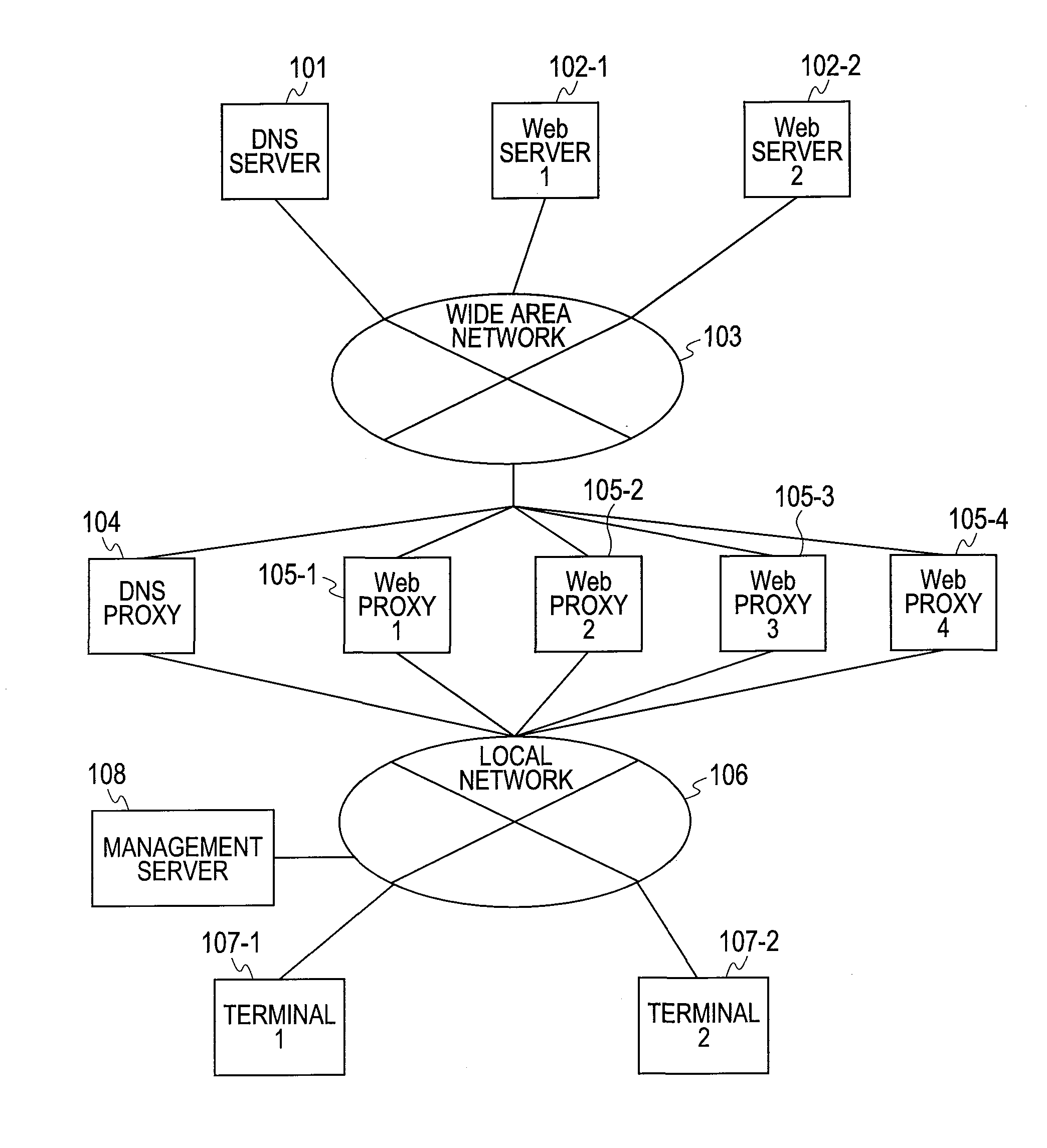
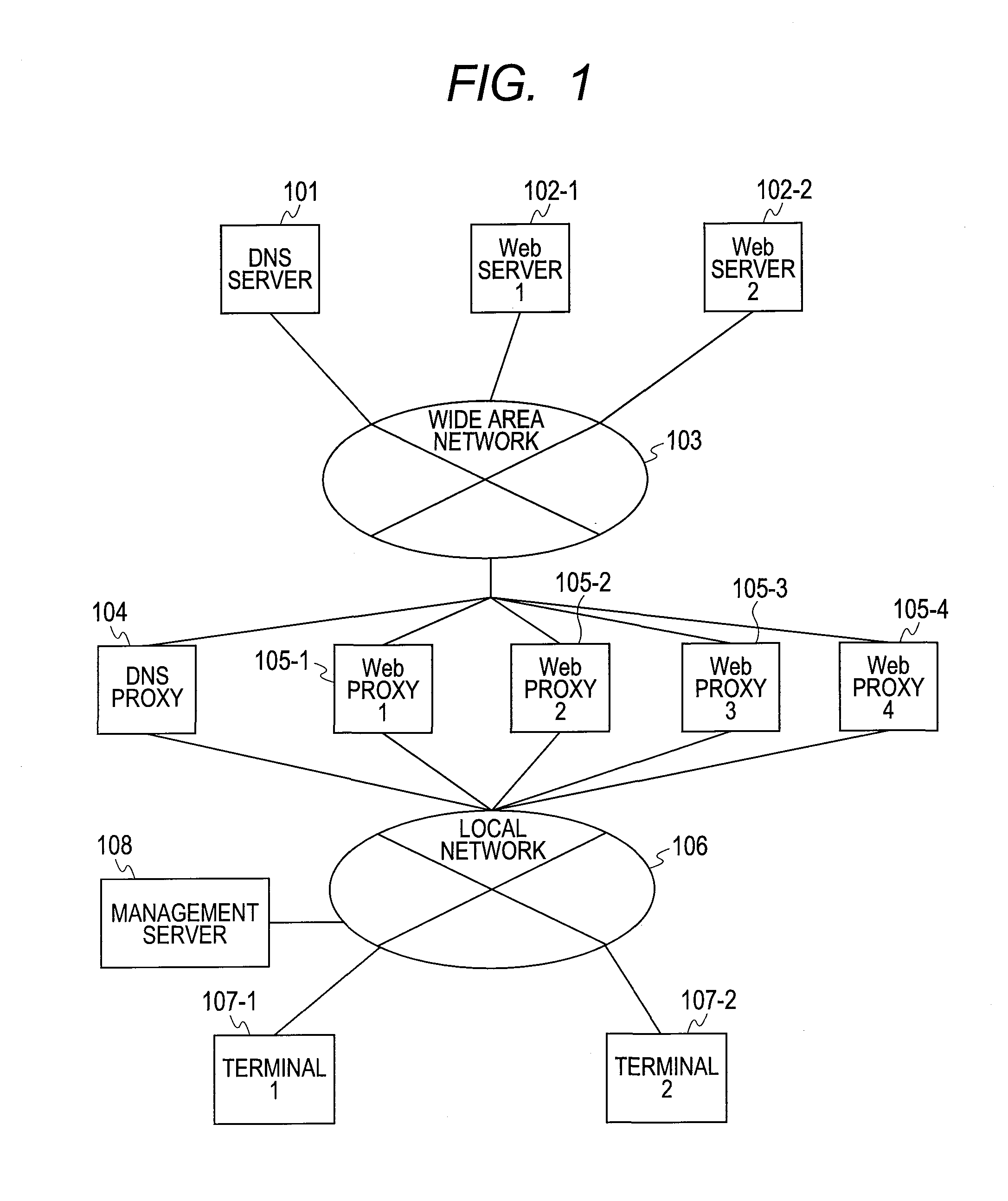
[0046]FIG. 1 is a drawing for describing the structure of the gateway system of the first embodiment of this invention.

[0047]The gateway system of the present embodiment contains a DNS proxy 104, multiple Web proxies (Web proxy 1_105-1, Web proxy 2_105-2, . . . ) and a management server 108. Each device mutually connects via a local network 106.

[0048]The DNS proxy 104 and the multiple Web proxies (Web proxy 1_105-1 and others) connect by way of the wide area network 103 to the DNS server 101, multiple Web servers (Web server 1_102-1, Web server 2_102-2, . . . ) to provide services to the multiple terminals (terminal 107-1, terminal 2_107-2, . . . ) connected to the local network 106. For example, request messages from the terminal 107_1 to the Web server 1_102-1 and reply messages from Web server 1_102-1 to the terminal 107_1 are sent and received via any of the Web proxies.

[0049]If jointl...

second embodiment

[0153]The structure of the gateway system of the second embodiment is the same as the gateway structure of the first embodiment shown in FIG. 1. The structure of the DNS proxy of the second embodiment is the same as the structure of the DNS proxy of the first embodiment shown in FIG. 3. The structure of the Web proxy of the second embodiment is the same as the Web proxy of the first embodiment shown in FIG. 5.

[0154]However a portion of the processing in the address converter processor unit of the DNS proxy of the second embodiment is different from the processing of the address converter processor unit of the first embodiment (S1404 and S1412 in FIG. 14). Moreover, a portion of the processing in the Web cache process function unit of the Web proxy of the second embodiment is different from the processing in the Web cache process function unit of the first embodiment (S1402 in FIG. 14).

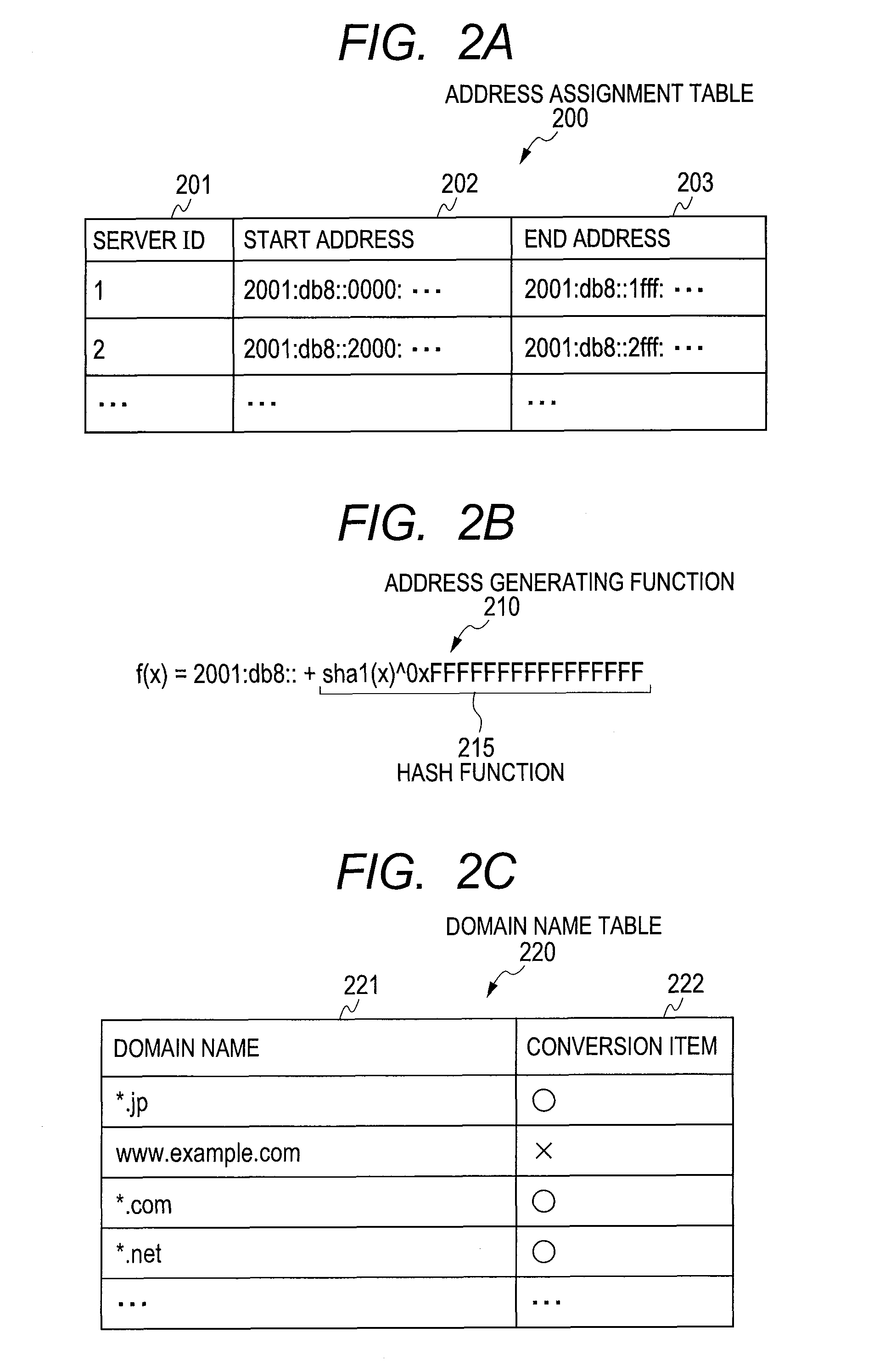
[0155]In the gateway system of the first embodiment, the DNS proxy 104 calculates the hash value fr...


PUM


Abstract

A gateway system for distributing requests from multiple terminals to multiple first servers includes a second server device and a name resolution device wherein: an address generating function for generating an IP address from a character string is distributed to the name resolution device, and multiple specified IP addresses are registered in the second server devices; when the name resolution device receives a first request for resolving a name, the name resolution device extracts the access destination URL from the first request, generates an IP address from the character string of the host name of the extracted URL by utilizing the address generating function, and sends the generated IP address to the terminal; and when the terminal sends a second request setting the access destination of the URL for the first server device, to the second server device where the IP address is registered, the second server device transfers that transmitted second request to the first server device based on the URL of the access destination.

Description

CLAIM OF PRIORITY[0001]The present application claims priority from Japanese patent application JP 2009-185624 filed on Aug. 10, 2009, the content of which is hereby incorporated by reference into this application.FIELD OF THE INVENTION[0002]The present invention relates to technology for load balancing in gateway systems for client-server type network services.BACKGROUND OF THE INVENTION[0003]Traffic processed by carrier gateways is vastly increasing due to boosted terminal performance and access networks that work at ever higher speeds. Carriers therefore attempt to increase the number of traffic lines to the Internet and to reduce traffic at the gateway by using information processing technology.[0004]The content cache is one type of information processing technology for reducing traffic. In this technology, when a terminal has requested contents from a server device (such as a Web server) over the Internet, a gateway server device (such as a Web proxy) temporarily stores the con...

Claims


Application Information

Patent Timeline
IPC IPC(8): G06F15/16
CPCH04L29/12066H04L29/12301H04L67/1002H04L61/2076H04L67/2814H04L61/1511H04L61/4511H04L61/5076H04L67/563H04L67/1001
Inventor TOUMURA, KUNIHIKO
Owner HITACHI LTD
Why Eureka
Try Eureka