Medical head restraint and medical bed system using the same

a head restraint and medical bed technology, applied in the field of medical head restraint and medical bed system using the same, can solve the problems of imposing heavy loads on the doctor and the patient, unable to image the flow of contrast medium into each region at a proper timing, and giving physical pain to an elderly patient or the like who canno

Active Publication Date: 2011-02-17
TOSHIBA MEDICAL SYST CORP
View PDF22 Cites 11 Cited by
  • Summary
  • Abstract
  • Description
  • Claims
  • Application Information

AI Technical Summary

Problems solved by technology

This imposes heavy loads on the doctor and the patient in imaging.
In addition, in some cases, it is impossible to image a contrast medium flowing into each region at a proper timing

Method used


Image

  • Medical head restraint and medical bed system using the same
  • Medical head restraint and medical bed system using the same
  • Medical head restraint and medical bed system using the same

Examples


Embodiment Construction

[0019]An embodiment will be described below with reference to the views of the accompanying drawing. Note that the same reference numerals denote constituent elements having almost the same functions and arrangements, and a repetitive description will be made only when required.

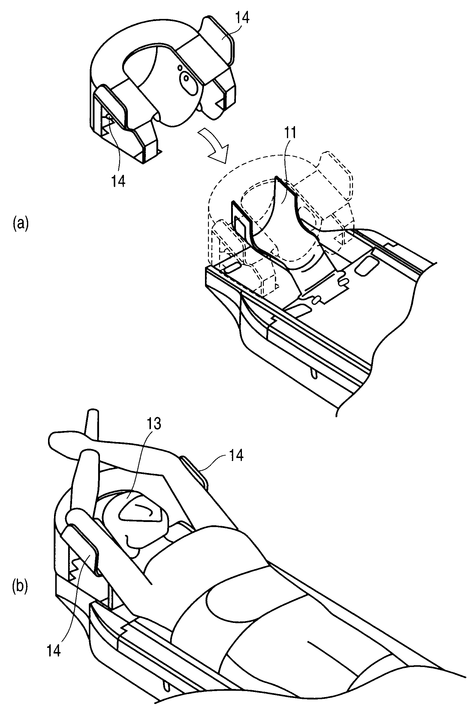
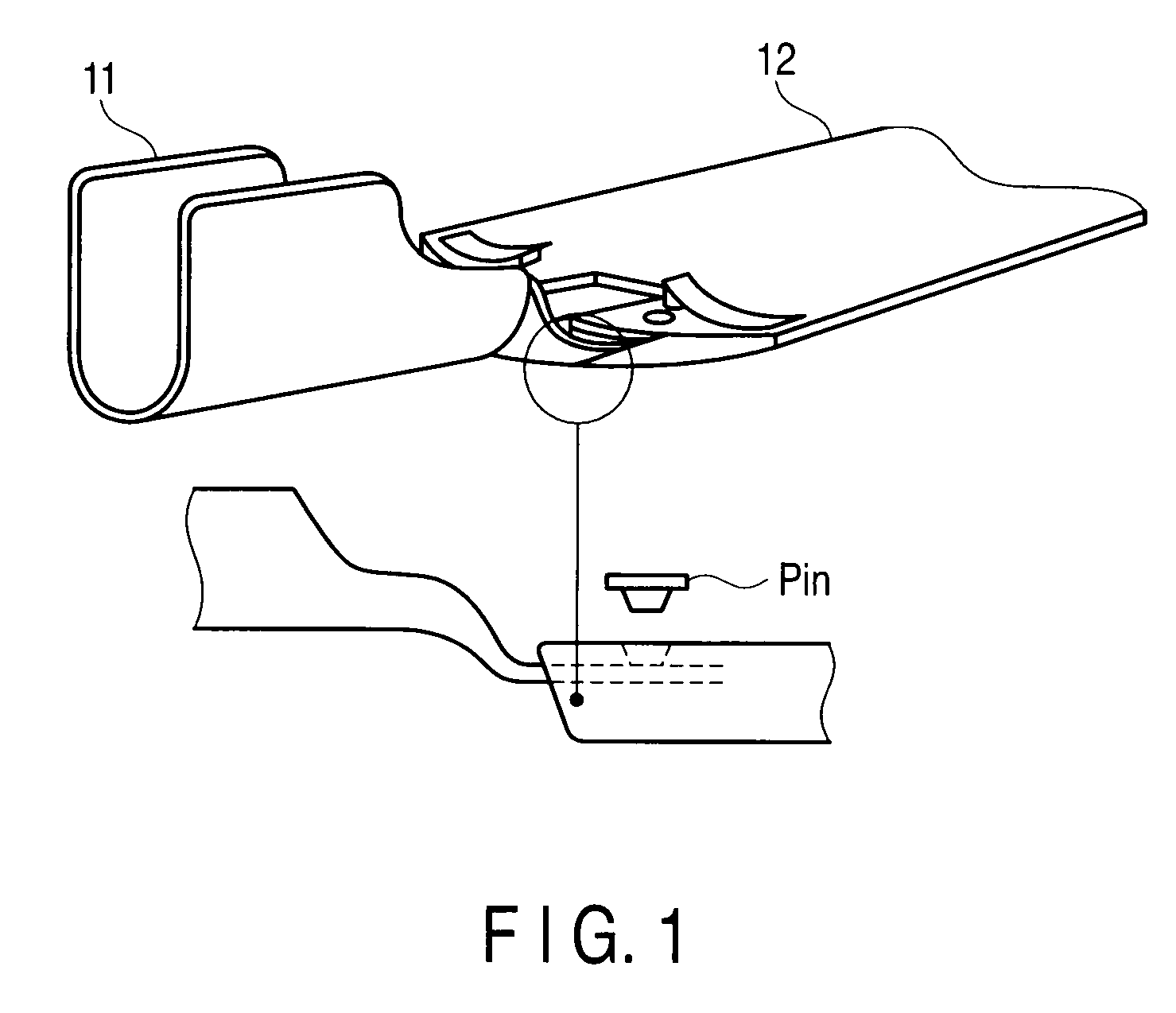
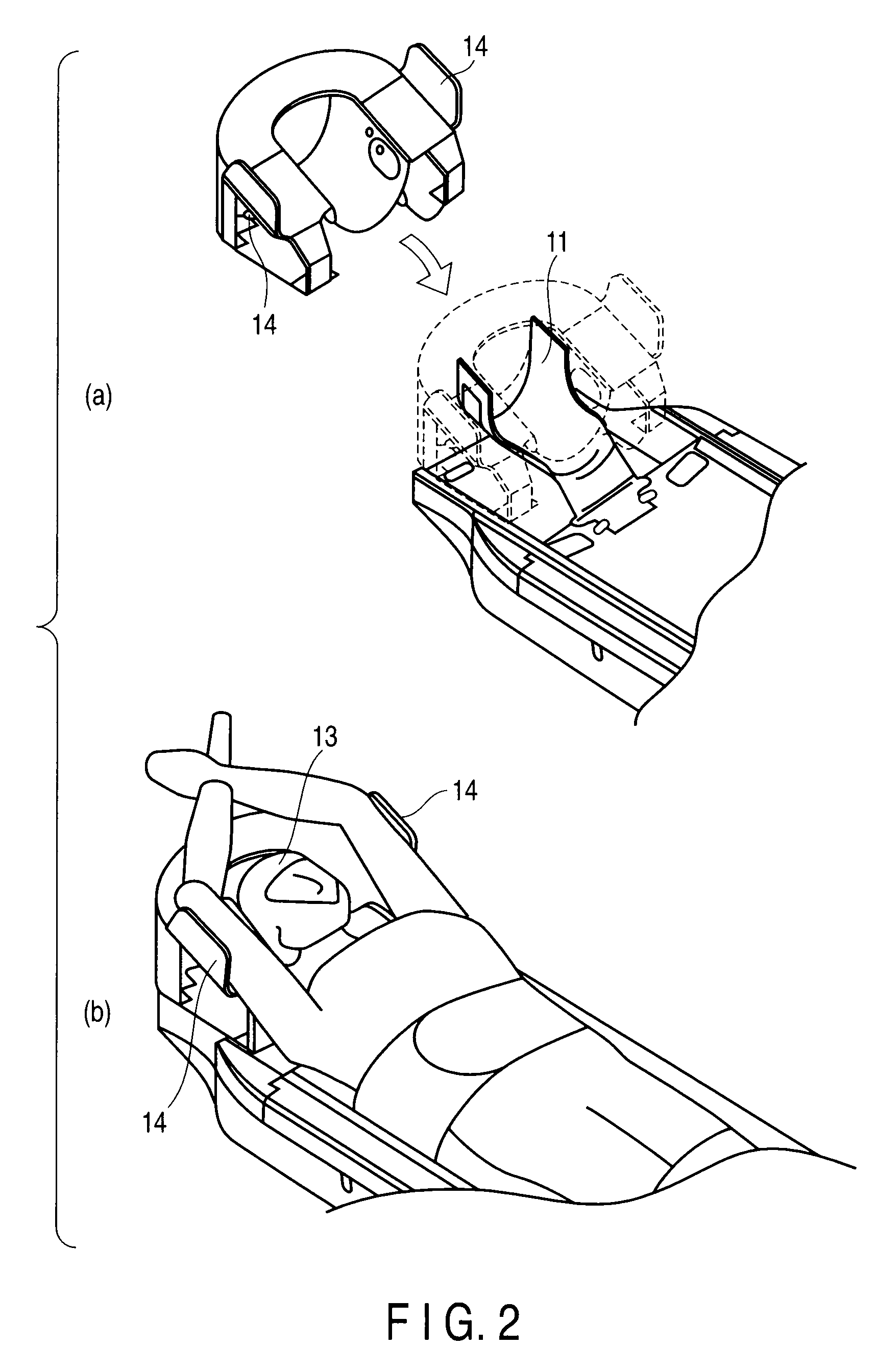
[0020]FIG. 3 is a perspective view showing an example of a head restraint 20 according to this embodiment. FIG. 4 is a perspective view showing a state in which the head is placed on the head restraint 20 according to the embodiment. FIG. 5 is a perspective view for explaining the structure of a head holding portion 22 of the head restraint 20 according to the embodiment. As shown in FIGS. 3, 4, and 5, the head restraint 20 includes a headrest portion 21, the head holding portion 22, and insertion holes 23a formed in the headrest portion 21 to allow grip handles 23b (to be described later) to be inserted therein.

[0021]The headrest portion 21 is made of a high-density foamed material such as polyurethane, plas...


PUM


Abstract

According to one embodiment, a head restraint attached to a top of a bed of one of a medical image diagnosis apparatus and a medical treatment apparatus, the head restraint comprises a headrest portion configured to allow a head of an object to be placed thereon, with the object being placed on the top, and an arm up holder configured to be detachable from the headrest portion and place an arm of the object near one of a vertex of the head of the object and a temple of the head when the head of the object is placed on the headrest portion.

Description

CROSS-REFERENCE TO RELATED APPLICATIONS[0001]This application is based upon and claims the benefit of priority from Chinese Patent Application No. 200910167040.4, filed Aug. 17, 2009; the entire contents of which are incorporated herein by reference.FIELD[0002]Embodiments described herein relate generally to a medical head restraint for restraining the head of a patient (object) placed on the bed of a medical image diagnosis apparatus, radiotherapy apparatus, or the like at a predetermined position or in a predetermined state, and a medical bed system including the medical head restraint.BACKGROUND[0003]Assume that a region to be imaged or the like is the head of a patient in image diagnosis using a medical image diagnosis apparatus typified by X-ray computed tomography apparatuses, magnetic resonance imaging apparatuses, and the like or medical treatment using a radiotherapy apparatus or the like. In this case, a head restraint is used to restrain the head of the patient on the top...

Claims


Application Information

Patent Timeline
IPC IPC(8): A61G13/12A61G15/00
CPCA61B6/0421A61G13/1235A61G13/121
Inventor LIJUN, WANG
Owner TOSHIBA MEDICAL SYST CORP
Why Eureka
Try Eureka