Footwear for walking or running with rolling action

a technology of rolling action and shoes, applied in the field of shoes, can solve the problems of difficulty in walking and not without risk, impede the widespread acceptance of shoes in the market, and prior art mbt shoes are not attractive in appearance, and achieve the effect of greater walking stability

a technology of rolling action and shoes, applied in the field of shoes, can solve the problems of difficulty in walking and not without risk, impede the widespread acceptance of shoes in the market, and prior art mbt shoes are not attractive in appearance, and achieve the effect of greater walking stability

US20110035960A1Active Publication Date: 2011-02-17XELERO TECH

Image

  • Footwear for walking or running with rolling action
  • Footwear for walking or running with rolling action
  • Footwear for walking or running with rolling action

Examples


Embodiment Construction

[0030]The shoe which inspired the present invention, the MBT shoe, is shown schematically in FIG. 8 in a lateral view. In the document PCT / CH00 / 00412, the MBT shoe is designated as “device for dynamic rolling walking”. It consists of an upper part 2 and the composite sole assembly 10 to 13. The number 10 represents the inner sole, which is solid, hard and elastic. Located beneath it is a lower sole, 11, which separates the midsole 10 from the undersole 12, which is soft and elastic. The sole bottom 13 is in contact with the surface on which the user walks.

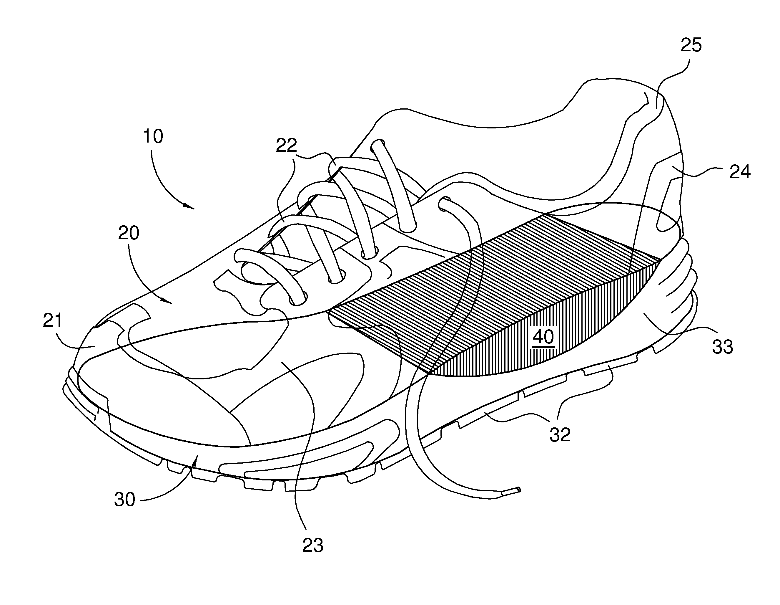
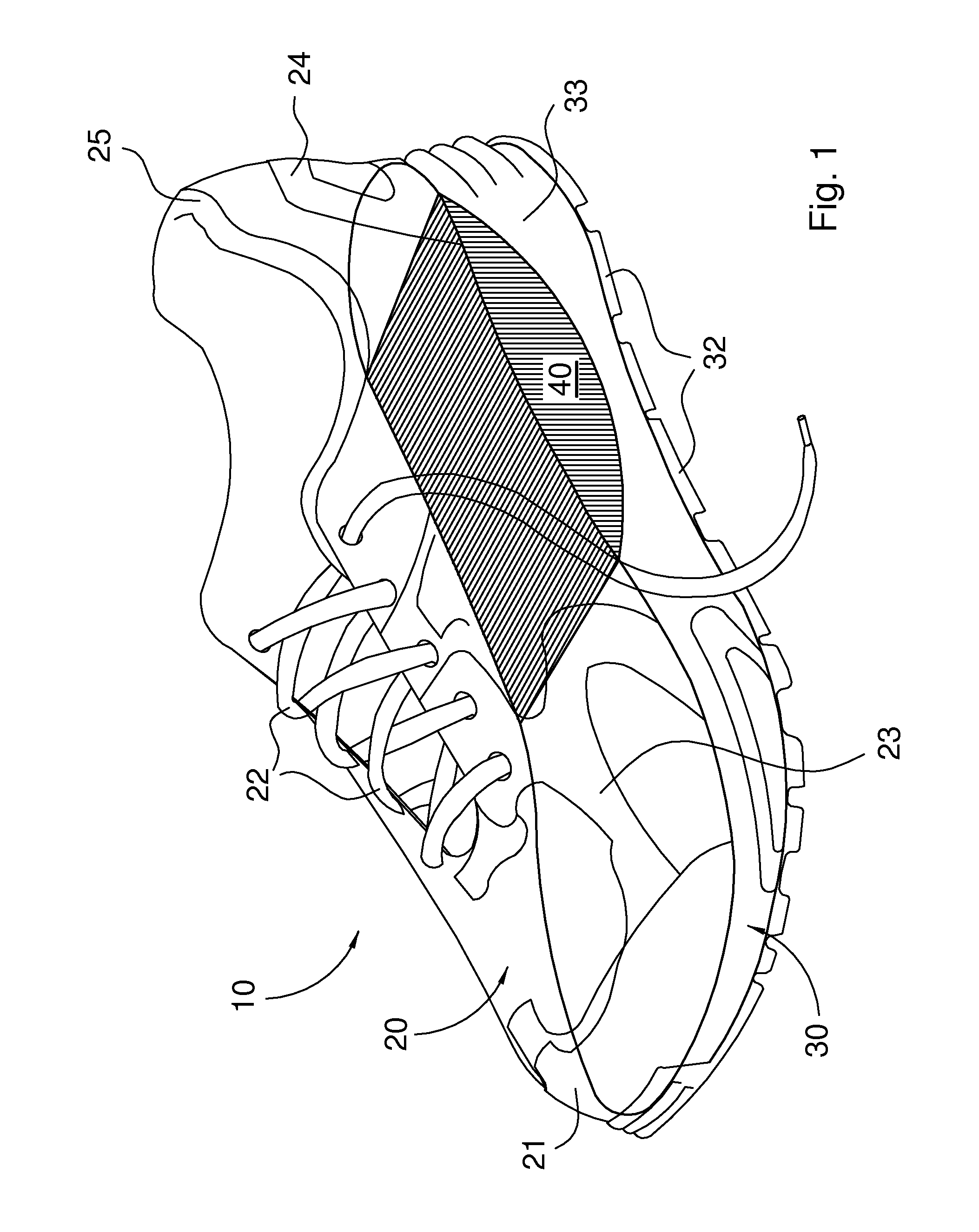
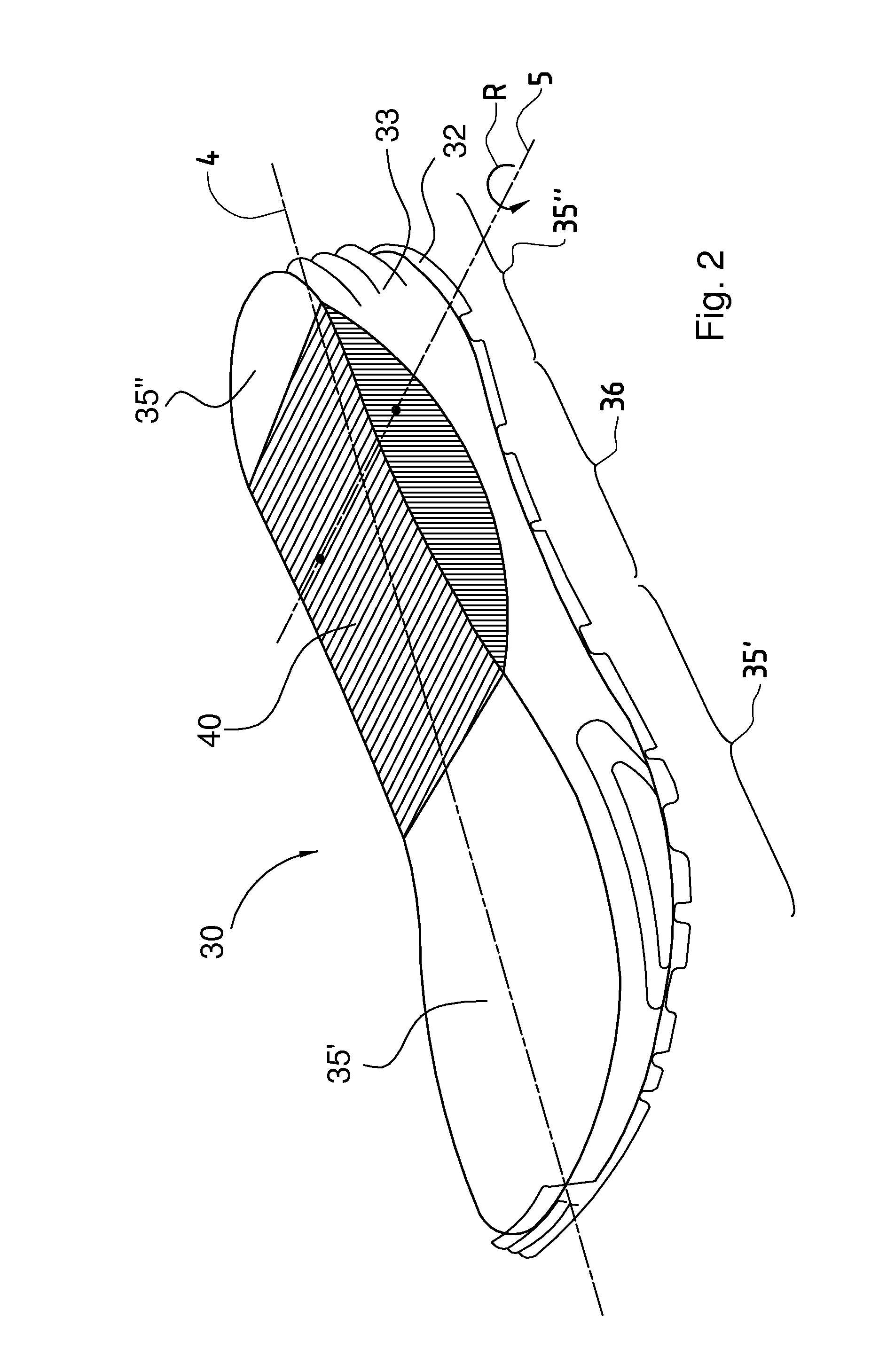
[0031]As described previously, the footwear sole assembly of the present invention aims to permit a similar, or improved, rolling gait to that achieved by the prior art MBT shoe illustrated in FIG. 8, but in a more conventionally-shaped sole.

[0032]The attached drawings are for illustrative purposes only, and are provided in order to aid an understanding of the invention. The figures are not intended to convey a limitation or defini...


PUM


Abstract

A footwear sole assembly (10) for walking with a rolling action is described. An elastically compressible midsole element (33) is provided with a rolling element (40) situated in and extending over a portion of the length and over at least a portion of the width of the midsole element (33). The rolling element (40) consists at least partially of a resilient material and is disposed at least in that region of the midsole (33) which is opposite to the arch of the wearer's foot. This shoe offers the rolling gait advantages of the well known MBT shoe, but has a different construction which enables it to retain the outward appearance of conventional shoes such as trainers.

Description

TECHNICAL FIELD[0001]This invention relates to footwear having a sole assembly which enables a wearer to walk with a rolling action.BACKGROUND ART[0002]The concept of walking with a rolling action is said to come from the Masai, an ethnic group in Kenya, who move barefoot with a particularly healthy gait. Footwear enabling this particular way of walking, even when wearing shoes, has been described in the patent application document WO01 / 15560A1 (PCT / CH00 / 00412). Further information about walking with a rolling action, in particular in the field of orthopaedics, is to be found for example in the article “MBT, Orthopädieschuhtechnik 12 / 2004”, pp. 22-28. MBT stands for “Masai Barefoot Technology”.[0003]The fundamentals of walking with a rolling action are described in the aforementioned document, therefore the benefits of walking with a rolling action and its positive effects on the human organism, in particular on the spine and the joints, will not be described here.[0004]Prior art MB...

Claims


Application Information

Patent Timeline
17 Feb 2011
Publication
US20110035960A1
IPC
A43B13/18
CPC
A43B7/142; A43B7/143; A43B13/026; A43B13/188; A43B13/145; A43B13/16; A43B13/12
Inventors
WERREMEYER, DANIEL; TIGHE, ROBERT