
Air purifying respirator having inhalation and exhalation ducts to reduce rate of pathogen transmission

a respirator and air purification technology, applied in the field of air purifying respirator masks, can solve the problems of respiratory masks that are difficult to clean, healthcare workers wearing respirator masks may be ill, and the filter is not enough

Inactive Publication Date: 2011-02-17
SCOTT TECH INC +1
View PDF8 Cites 35 Cited by
  • Summary
  • Abstract
  • Description
  • Claims
  • Application Information

AI Technical Summary

Problems solved by technology

But, the filters on the masks only serve to concentrate the respirable particles of pathogen on the filter media and non-respirable particles on surfaces directly exposed to droplet spray and contact.
Many known filters are difficult to clean without damaging the filter media, therefore requiring change out of the filter prior to its normal end of service life to avoid contact exposure and transmission to non-infected patients and the wearer.
This places an extra demand for filters and during a pandemic scenario lead to shortages of filters for masks.
Conversely, the healthcare worker that is wearing the respirator mask may be ill.
The droplet spray can contaminate surfaces immediately in front of the wearer including another person who is interacting with the healthcare worker.
Thus, some known filter masks do not adequately protect both the people who wear the filter masks and the people who are interacting with those wearing the filter masks from some potential routes of transmission.
The air being filtered is inhaled from the direction of the potentially infected individual and the filter is not protected from surface contamination due to droplet spray.
This burdens the filter with a higher concentration of respirable particles to filter and requires filter change out to avoid infection of the wearer or other individuals due to surface contamination of the filter surface.
Similarly, contaminated air may be exhaled by persons wearing the masks and infect those persons who are interacting with the persons wearing the masks.

Method used


Image

  • Air purifying respirator having inhalation and exhalation ducts to reduce rate of pathogen transmission
  • Air purifying respirator having inhalation and exhalation ducts to reduce rate of pathogen transmission
  • Air purifying respirator having inhalation and exhalation ducts to reduce rate of pathogen transmission

Examples


Embodiment Construction

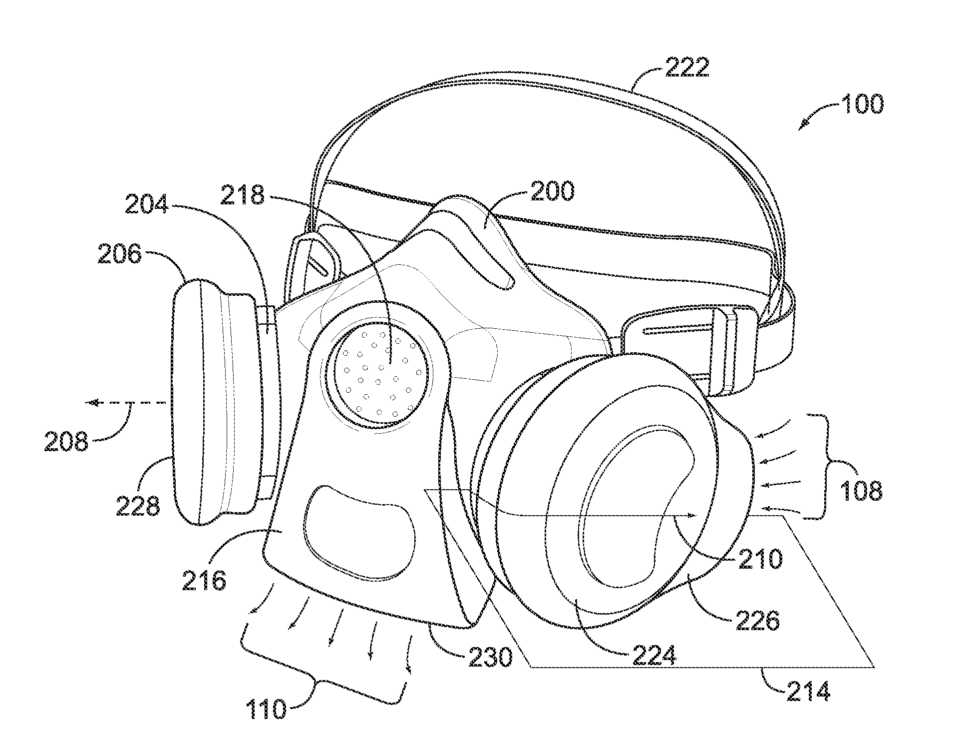
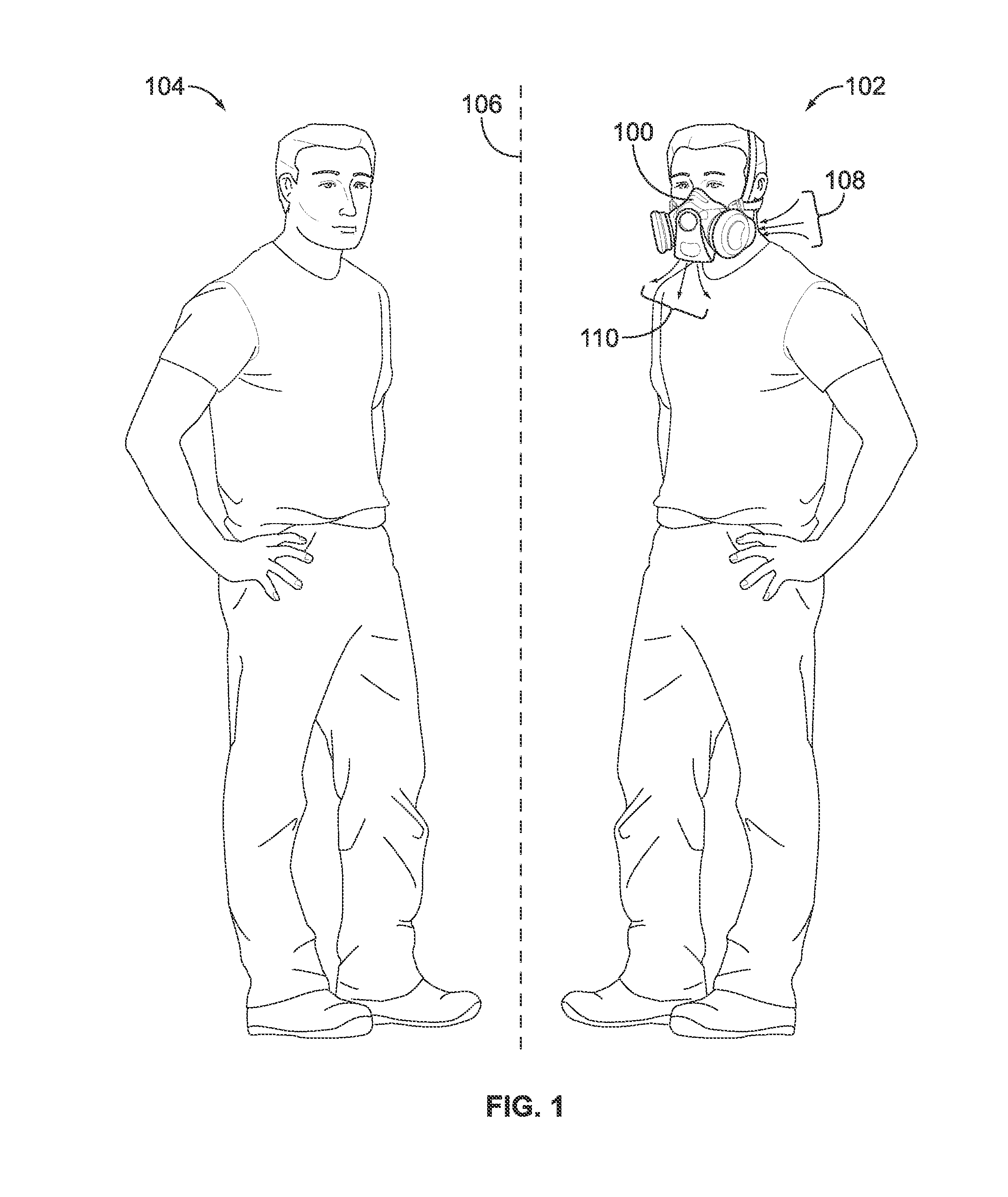
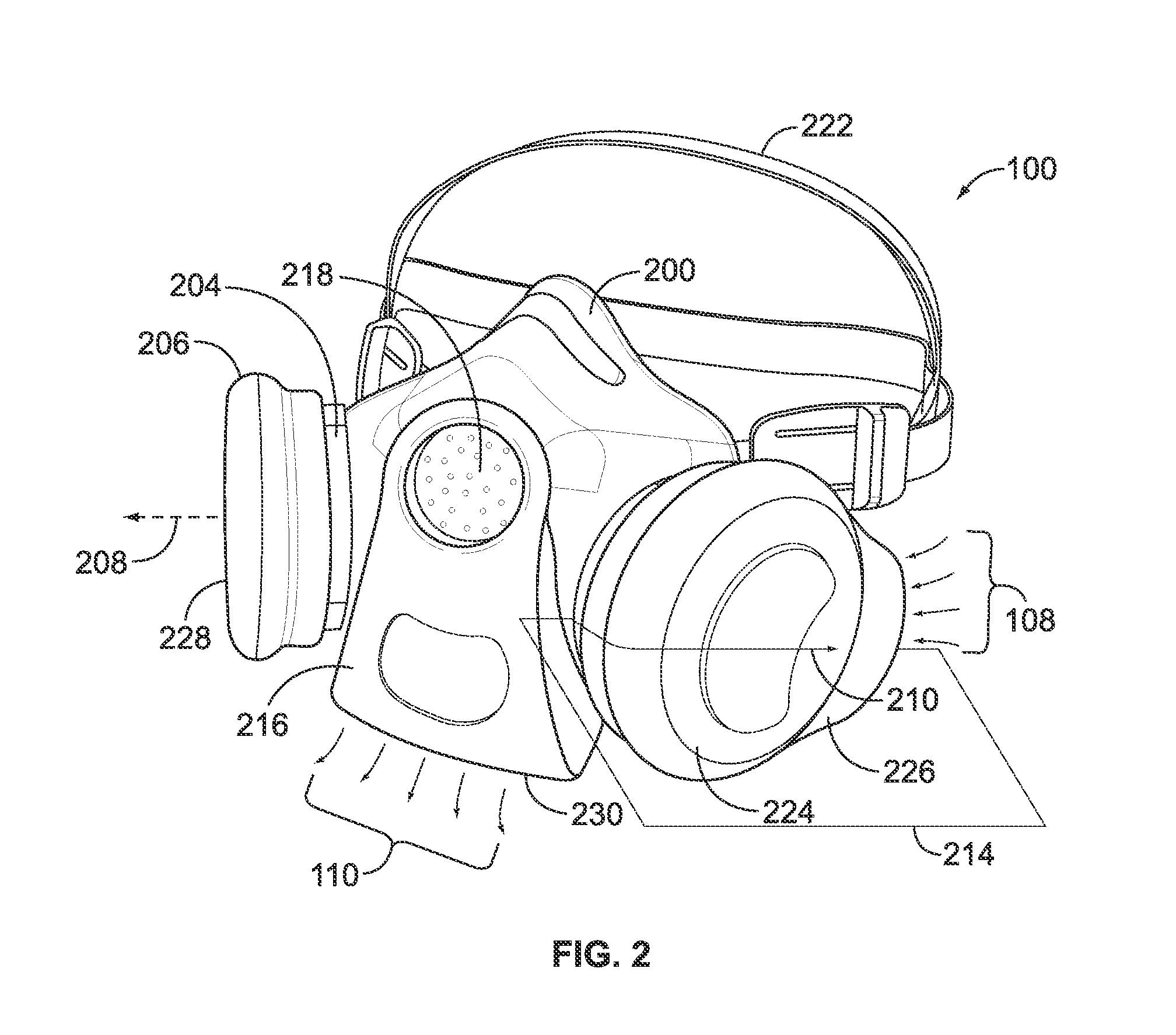
[0027]FIG. 1 is an illustration of a human user 102 wearing a filter mask, or respirator, 100 during interaction with another person 104 in accordance with one embodiment of the present disclosure. The filter mask 100 protects the user 102 that is wearing the filter mask 100 from inhalation of airborne contaminants, such as foreign bodies, pathogens, bacteria, toxins, aerosols, and contamination of the oronasal region by droplet spray by controlling the direction(s) in which air is inhaled into the mask 100. The filter mask 100 may protect other persons 104 from air that is exhaled by the user 102 from the filter mask 100 by controlling the direction(s) in which the exhaled air is directed. For example, the user 102 may be a healthcare professional and the user 104 may be a patient being examined or treated by the user 102. A plane of interaction 106 is a spatial plane or interface between the users 102, 104 and through which the users 102, 104 interact. By way of example only, the ...


PUM


Abstract

A filter mask includes an oronasal cup, an inhalation directional cover, and an exhalation diverter body. The oronasal cup encloses a nose and mouth of a user. The oronasal cup is fluidly coupled with a filter. The inhalation directional cover is configured to be joined to the filter. The inhalation directional cover includes an elongated wing portion that is oriented in an inhalation direction that is angled with respect to the center axis of the filter. The exhalation diverter body is fluidly coupled with the oronasal cup. The exhalation diverter body defines an exhalation duct that directs exhaled air out of the oronasal cup along an exhalation direction. The inhalation direction and the exhalation direction are oriented away from a plane of interaction between the user and another person.

Description

CROSS-REFERENCE TO RELATED APPLICATIONS[0001]This application claims priority benefit from U.S. Provisional Application Ser. No. 61 / 234,136, filed Aug. 14, 2009, and entitled “Filter Mask” (the “'136 Application”). The subject matter and disclosure of the '136 Application is hereby incorporated by reference in its entirety.BACKGROUND OF THE INVENTION[0002]The subject matter herein relates generally to air purifying respirator masks, and more particularly, to respirator masks that filter inhaled and / or exhaled air.[0003]Masks such as respirator masks may be worn by individuals who wish to protect themselves from toxic airborne contaminants such as particulates, vapors and gases. Particulates may be airborne pathogens, toxins, aerosols, and the like. For example, some known filter masks include filters that remove contaminants from air that is inhaled into the masks. Some known filter masks include one or more filters. The filters may be joined to the mask on either side or both sides...

Claims


Application Information

Patent Timeline
IPC IPC(8): A62B7/10
CPCA62B18/025
Inventor MORGAN, III, JUDGE WOODROWSTAUBS, AMY ELIZABETHPARHAM, MICHAELOWENS, SIONEDAUSTERBERY, SEANROBERTS, GARETHBAKER, TROY ALAN
Owner SCOTT TECH INC
Learn More