Rock drilling device

Inactive Publication Date: 2011-02-17
ATLAS COPCO ROCK DRILLS
View PDF27 Cites 5 Cited by
  • Summary
  • Abstract
  • Description
  • Claims
  • Application Information

AI Technical Summary

Benefits of technology

[0013]The present invention has the advantage that switching between drilling and subsequent bolting can occur easily because the feed beam is moved linearly in a direction separate from the drilling direction.

Problems solved by technology

Rock bolting is often done with bolts over 1 meter in length, and when a rock drilling rig is used for bolting in low/narrow galleries it can be hard

Method used


Image

  • Rock drilling device
  • Rock drilling device
  • Rock drilling device

Examples


Embodiment Construction

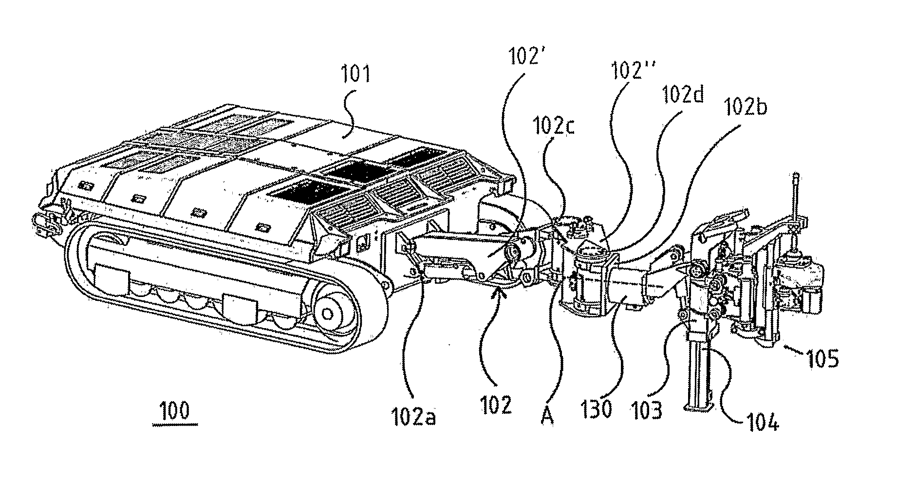
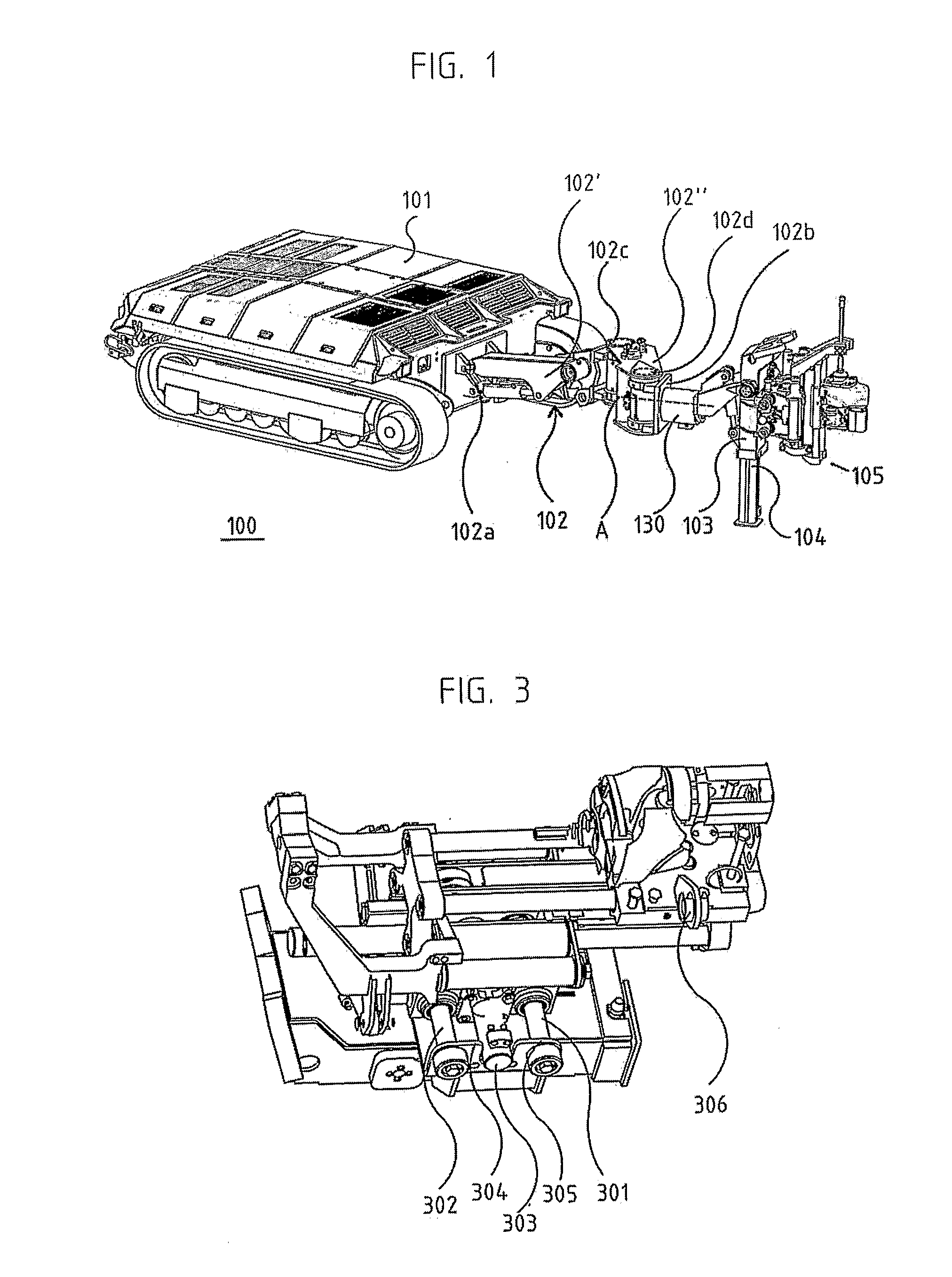
[0021]FIG. 1 shows a mining machine of the present invention in the form of a rock drilling rig 100, which is especially suitable to be used in drilling and / or bolting when working in very low galleries. For example, there are galleries with a height on the order of 1.2 m, where bolting has to be done with bolt lengths of 1.6 m, for example, to reduce the risk of a cave in.

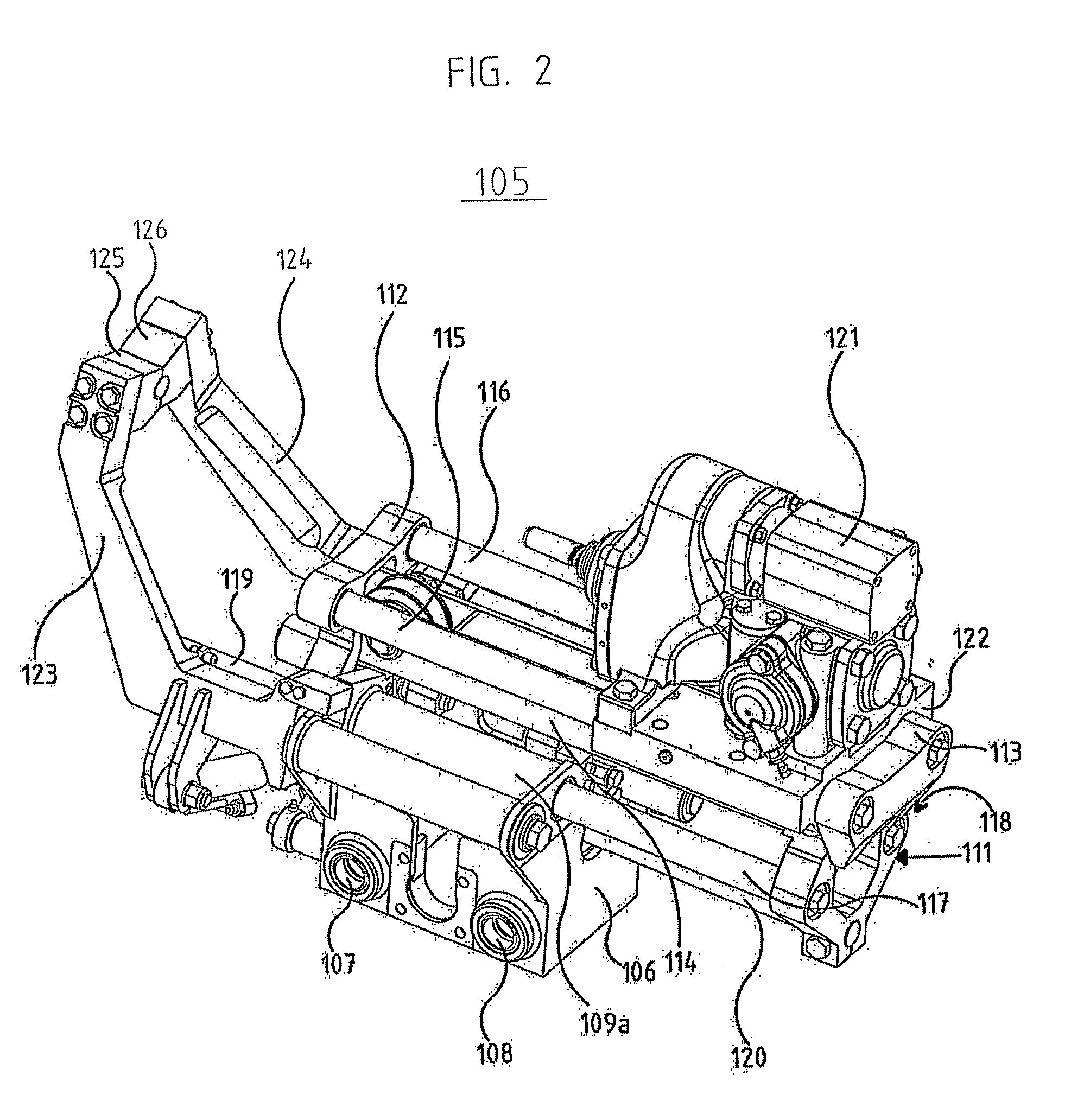
[0022]The rock drilling rig 100 shown consists of a carrier 101 and a boom 102, whose one end 102a is fastened to the carrier. The boom 102 consists of two sections 102′, 102″, joined by a rotational linking means 102c to afford great freedom of adjustment during drilling, while at the same time the outer boom section 102″ can retract to facilitate moving around (e.g., by reducing the risk of hitting the surrounding rock). At the end 102b of the boom 102 away from the carrier 101, a drilling support 103 with support leg 104 is arranged. To the drilling support 103 is fastened a feed unit 105 comprising a feeder ho...


PUM


Abstract

The present invention pertains to a feeder holding device to be used with a rock drilling and/or rock bolting rig, wherein said rock drilling and/or rock bolting rig comprises at least one boom with a first end and a second end, wherein said first end is attached to a carrier, and said second end is designed to support a feed beam by means of the feeder holding device, wherein said feed beam can be adjusted by means of said feeder holding device in a first drilling position in a first drilling direction and in a second position. The feeder holding device is designed for linear movement of said feed beam, in a direction different from said drilling direction, from said first drilling position to said second position, wherein the feed beam in said second position is pointed in a direction parallel to said first drilling direction. The invention also pertains to a rock drilling and/or rock bolting rig.

Description

FIELD OF THE INVENTION [0001]The present invention pertains to a feeder holding device to be used in drilling and / or bolting. In particular, the present invention pertains to a feeder holding device according to the preamble of claim 1. The invention also pertains to a rock drilling and / or rock bolting rig according to claim 9.BACKGROUND OF THE INVENTION[0002]In rock drilling and rock bolting, one often uses a rock drilling rig where one or more drilling machines are carried by respective movable arms, or booms. The booms are usually flexibly attached to a carrier, such as a vehicle, via one or more joints. Furthermore, the drilling machine is usually flexibly attached to the end of the boom away from the carrier via one or more additional joints.[0003]The drilling machine is usually not attached directly to the boom, instead being normally attached to the boom displaceable by a feed unit, for example, consisting of a feeder holder, which carries a feed beam arranged movably relativ...

Claims


Application Information

Patent Timeline
IPC IPC(8): E21B3/02
CPCE21D20/003E21B7/025E21B7/02E21B15/00
Inventor NYSTROM, SVEN-OLOV
Owner ATLAS COPCO ROCK DRILLS
Why Eureka
Try Eureka