Multi-Link Bridge In Undercarriage System

a multi-link bridge and undercarriage technology, applied in the field of undercarriage systems, can solve the problems of reducing a durability and a riding feeling, and achieve the effects of preventing a vibration, enhancing the riding feeling of operators, and preventing an overturning

Inactive Publication Date: 2011-02-17
DONG IL RUBBER BELT CO LTD
View PDF1 Cites 14 Cited by
  • Summary
  • Abstract
  • Description
  • Claims
  • Application Information

AI Technical Summary

Benefits of technology

[0003]It is an object of the present invention, to solve the above problems, to provide a multi-link bridge in an undercarriage system capable of preventing a vibration and an inclination of a vehicle body occurred by a condition of an uneven road surface thereby enhancing operator's feeling of riding as well as preventing an overturning and capable of preventing a partial wear of a track thereby enhancing a durability by designing a center frame and a roller frame independently from each other and adding a plurality of links to the frame connecting portion so that the roller frame is relatively movable independently from the center frame in a up and down direction and a front and rear direction respectively.Technical Solution

Problems solved by technology

Generally, an undercarriage system, with a shape in which a center frame and a roller frame are connected to each other, of conventional excavators have had problems that if there are uneven road surfaces in a work place, an inclination of an overall excavator is occurred as the center frame and the roller frame are inclined simultaneously according to a condition of the uneven road surfaces and thus there are a dangerousness due to an overturning of a vehicle body, a decrease of a durability due to an accompanying partial wear by a load of a vehicle body and a decrease of a feeling of riding.

Method used


Image

  • Multi-Link Bridge In Undercarriage System
  • Multi-Link Bridge In Undercarriage System
  • Multi-Link Bridge In Undercarriage System

Examples


Embodiment Construction

[0016]Practical and presently preferred embodiments of the present invention are illustrative as shown in the following Examples. A pigment mixed in melted resin is exemplary a flake type pigment in the present description; however it will be appreciated that besides the flake type a polyhedron type pigment or a different type of pigment may also be employed.

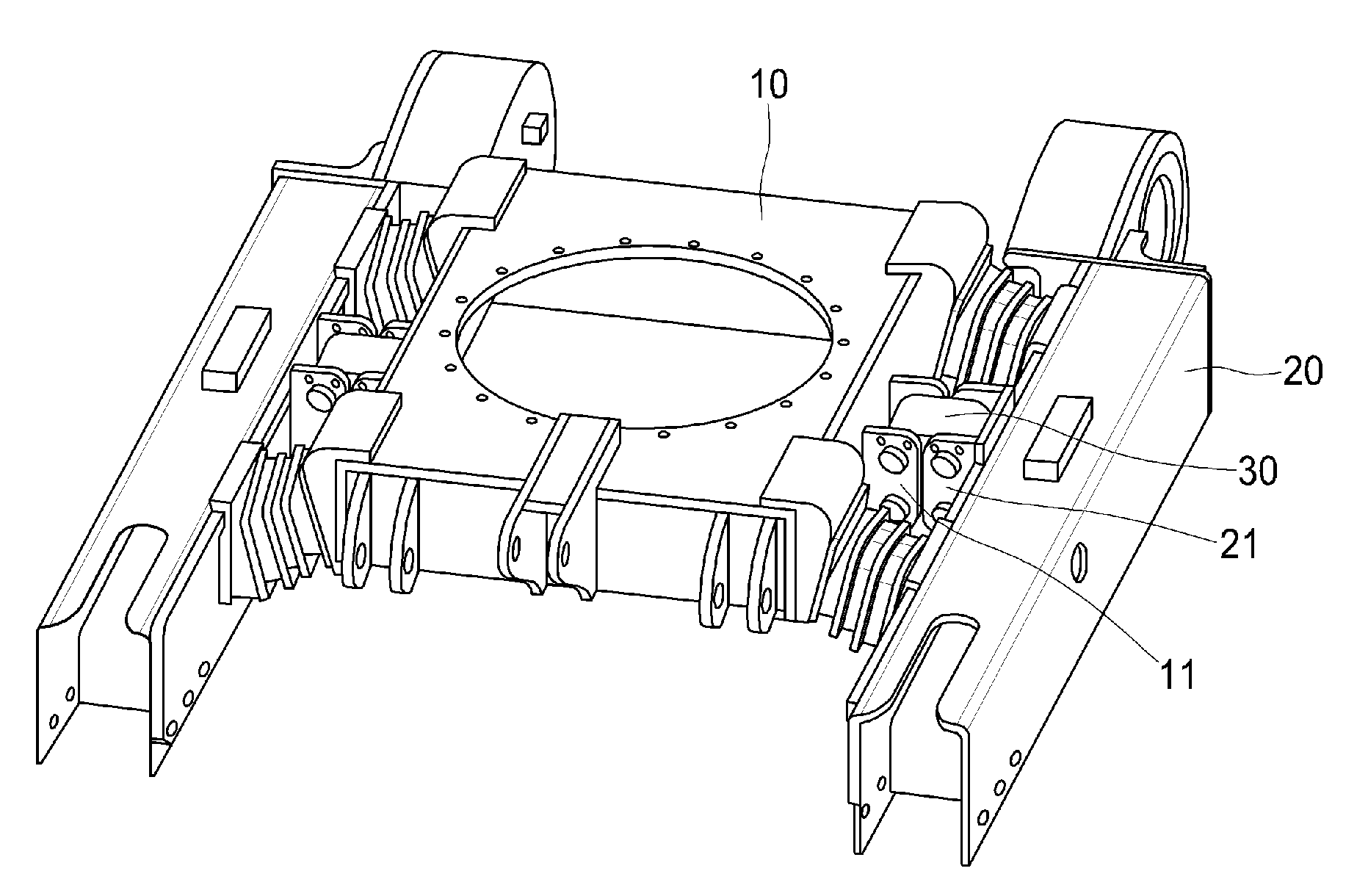
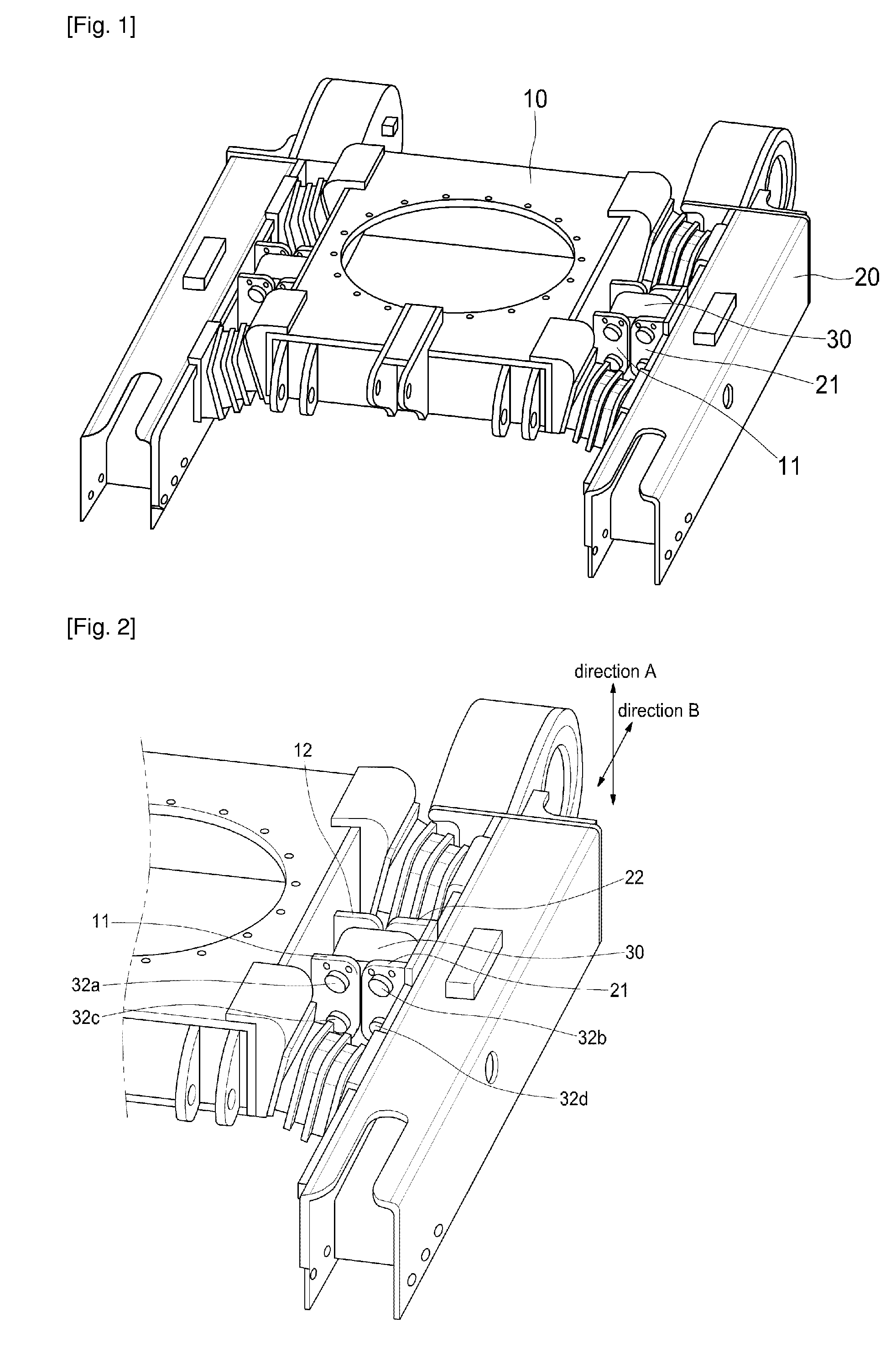
[0017]FIG. 1 is a perspective view illustrating an entire undercarriage system employing a multi-link bridge according to a preferred embodiment of the present invention and FIG. 2 is an enlarged perspective view illustrating a structure of a connecting portion which connects a center frame and a roller frame of FIG. 1; shown is a state that two multi-link bridges 30 are coupled in a laminated structure to link connection brackets 11, 12, 21 and 22 so as to couple the center frame 10 and the roller frame 20 in duplicate, and shown is the undercarriage system in which a movement of the roller frame 20 is, as shown in FIG. 2, inde...


PUM


Abstract

The present invention employs a multi-link to an excavator for the first, and restricts a relative movement of the center frame (10) and the roller frame (20) using a multi-link bridge (30) in relation to an undercarriage system of vehicle body structures of the excavator. According to the present invention, in an undercarriage system in which the center frame 10 and the roller frame 20 are independently from each other, a plurality of links is added to rotate up and down by a predetermined angle in a vertical direction and a longitudinal direction of the roller frame (20) and thus the overturning can be prevented and also operator's feeling of riding can be enhanced by preventing an inclination of the center frame (10) due to condition of an uneven road surface, and a service life of the track can be increased as the partial wear is prevented.

Description

TECHNICAL FIELD[0001]The present invention relates to an undercarriage system, and more particularly, to a multi-link bridge in an undercarriage system, capable of preventing effectively an inclination of a roller frame in a vertical direction occurred from a load of a vehicle body and a condition of an uneven road surface and thus preventing an overturning of an excavator and a partial wear of a track thereby enhancing a service life and a feeling of riding by designing a center frame and the roller frame in an independent shape and connecting the center frame and the roller frame in an independent shape by the multi-link bridge so that both frame are independently movable in an up and down direction and a front and rear direction.BACKGROUND ART[0002]Generally, an undercarriage system, with a shape in which a center frame and a roller frame are connected to each other, of conventional excavators have had problems that if there are uneven road surfaces in a work place, an inclinatio...

Claims


Application Information

Patent Timeline
Patent Type & Authority Applications(United States)
IPC IPC(8): B62D55/104E02F9/08
CPCB62D55/084E02F9/024H01L21/67363H01L21/67386
Inventor CHO, JOON-ILSEON, JIN-GYUPARK, DONG-HWA
Owner DONG IL RUBBER BELT CO LTD
Why Eureka
Try Eureka