Liquid spray bottle with integrally molded liquid passageway and related methods

a liquid spray bottle and liquid passageway technology, applied in the field of bottles, can solve the problems of increasing the usage cost of users, increasing the amount of solid waste, and creating a potentially hazardous waste stream, and achieve the effect of increasing the amount of liquid

Inactive Publication Date: 2011-02-17
K&E HLDG
View PDF22 Cites 24 Cited by
  • Summary
  • Abstract
  • Description
  • Claims
  • Application Information

AI Technical Summary

Benefits of technology

[0011]This and other objects, features, and advantages in accordance with the present invention are provided by a spray bottle assembly which may include a spray head including a spray pump and a spray head tube extending downwardly therefrom. The spray bottle assembly may also include a spray bottle having an open upper end receiving the spray head, for example. The spray bottle may have a base and at least one sidewall extending upwardly therefrom. The at least one sidewall may have an integrally formed liquid passageway therein having an upper opening coupled in fluid communication with the spray head tube, and may have a lower liquid pick-up opening adjacent the base, for example. Accordingly, the spray bottle assembly is reusable and advantageously removes an increased amount of liquid from the spray bottle.

Problems solved by technology

Attempts to deplete or use residual liquid within spray bottle often involve a user operating the spray bottle assembly in an awkward direction, for example facing upward, and often do not result in a complete removal of the liquid.
Thus, the spray bottle assembly is generally discarded with residual liquid waste therein resulting in an increased usage cost for the user.
Moreover, discarding of spray bottle assemblies contributes to environmental pollution by creating an increased amount of solid waste and a potentially hazardous waste stream.
Moreover, residual liquid waste within the spray bottle when the spray bottle assembly is discarded may further contribute to the creation of hazardous waste and pollution.

Method used


Image

  • Liquid spray bottle with integrally molded liquid passageway and related methods
  • Liquid spray bottle with integrally molded liquid passageway and related methods
  • Liquid spray bottle with integrally molded liquid passageway and related methods

Examples


Embodiment Construction

[0029]The present invention will now be described more fully hereinafter with reference to the accompanying drawings, in which preferred embodiments of the invention are shown. This invention may, however, be embodied in many different forms and should not be construed as limited to the embodiments set forth herein. Rather, these embodiments are provided so that this disclosure will be thorough and complete, and will fully convey the scope of the invention to those skilled in the art. Like numbers refer to like elements throughout, and prime notation is used to indicate similar elements in alternative embodiments.

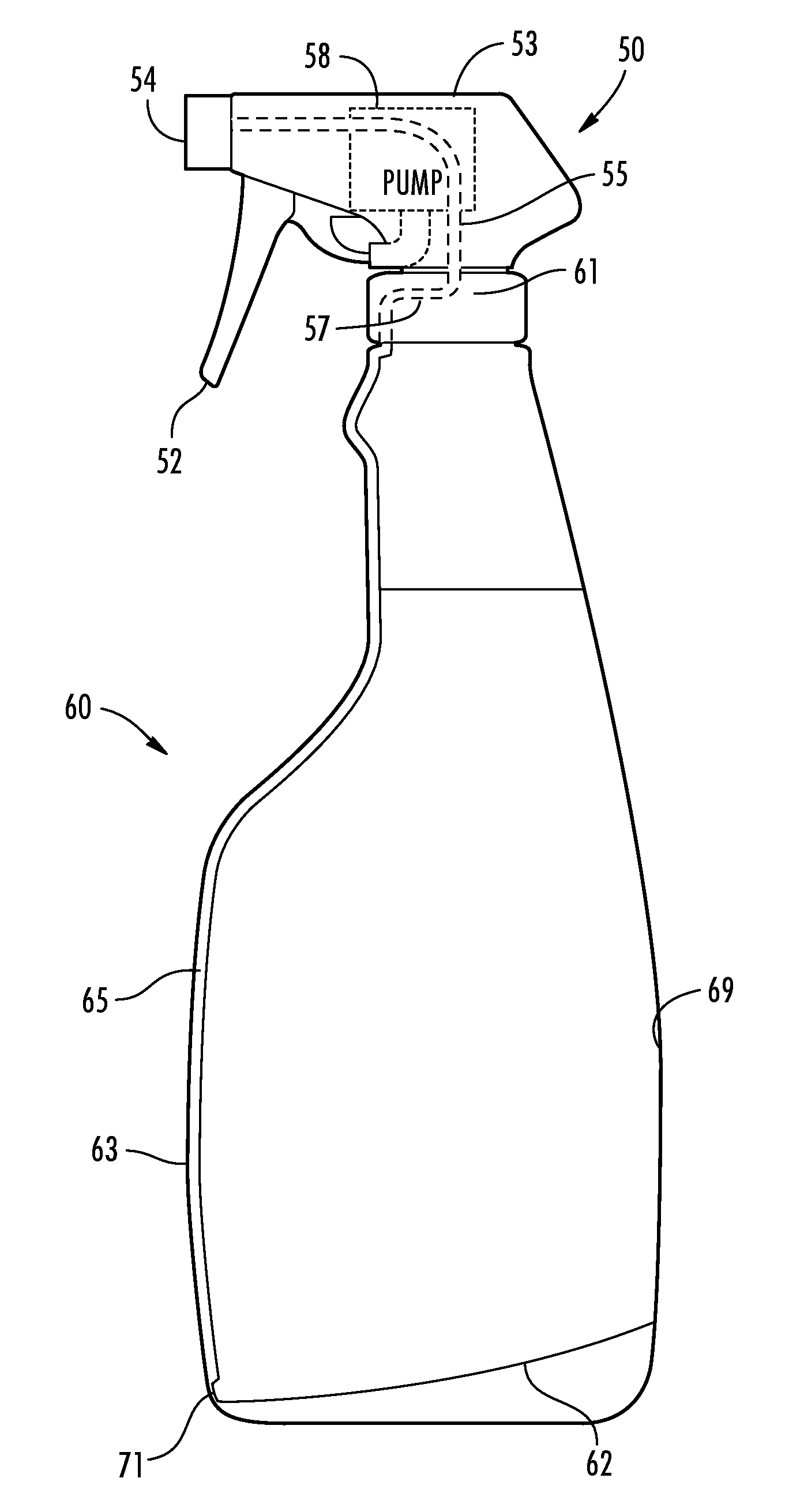
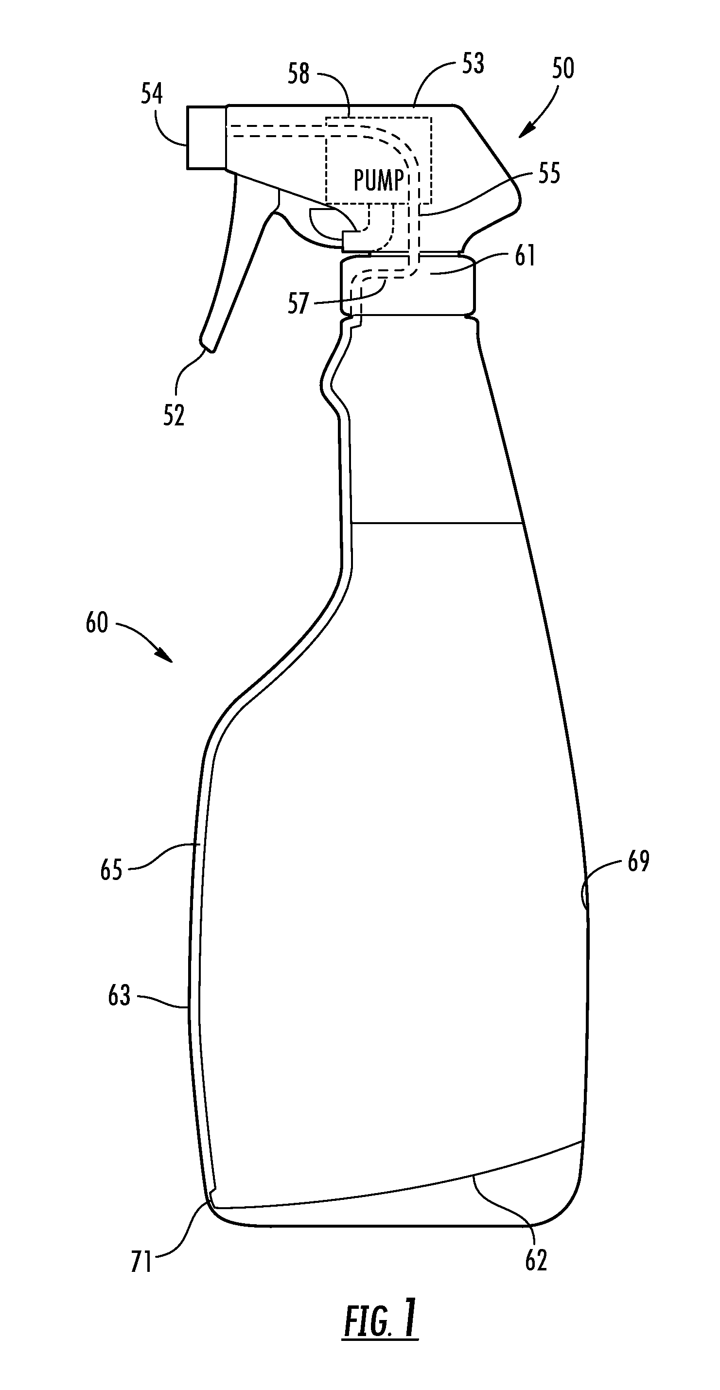
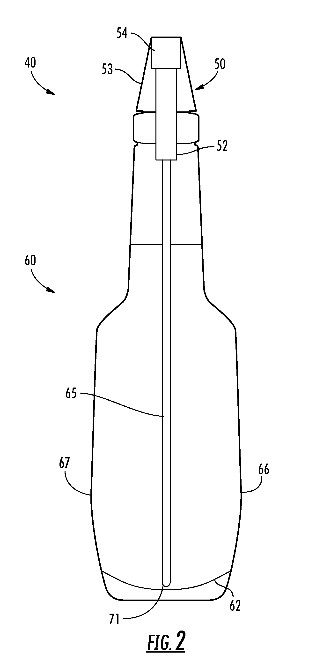
[0030]Referring initially to FIGS. 1-9, a spray bottle assembly 40 illustratively includes a spray head 50 coupled to a spray bottle 60. The spray bottle 60 is illustratively a plastic spray bottle, but may be other materials, as will be appreciated by those skilled in the art. The spray bottle 60 includes a base 62 and opposing front and rear sidewalls 63, 69 extending upw...


PUM

PropertyMeasurementUnit
rotationaaaaaaaaaa
shapeaaaaaaaaaa
sizesaaaaaaaaaa

Abstract

A spray bottle assembly may include a spray head including a spray pump and a spray head tube extending downwardly therefrom. The spray bottle assembly may also include a spray bottle having an open upper end receiving the spray head. The spray bottle may have a base and at least one sidewall extending upwardly therefrom. The at least one sidewall may have an integrally formed liquid passageway therein having an upper opening coupled in fluid communication with the spray head tube, and may have a lower liquid pick-up opening adjacent the base.

Description

RELATED APPLICATION[0001]The present application is based upon previously filed copending provisional application Ser. No. 61 / 234,007, filed Aug. 14, 2009, the entire subject matter of which is incorporated by reference in its entirety.FIELD OF THE INVENTION[0002]The present invention relates to the field of bottles, and, more particularly, to liquid spray bottles and related methods.BACKGROUND OF THE INVENTION[0003]A spray bottle assembly is generally used to squirt, spray or mist a fluid. For example, a common use for a spray bottle assembly is to dispense a cleaner, a cosmetic, and a chemical. Another example of a common use of a spray bottle assembly is to mix down concentrates with water.[0004]A typical spray bottle assembly, for example, includes a plastic spray bottle to hold the fluid coupled with a spray head to spray, mist, or otherwise deliver the fluid from the spray bottle. A plastic spray bottle may come in various sizes and shapes, may also come in various colors, and...

Claims


Application Information

Patent Timeline
Patent Type & Authority Applications(United States)
IPC IPC(8): B05B9/03
CPCB05B11/0037B05B11/3047Y10T29/49B05B15/005B05B15/066B05B11/3057B05B15/652B05B15/30B05B11/1057B05B11/1047
Inventor HENSEN, ERIC L.
Owner K&E HLDG
Why Eureka
Try Eureka