LED optical system

a technology of led optical system and led light, which is applied in the direction of semiconductor devices for light sources, fixed installations, lighting and heating apparatus, etc., can solve the problems of insufficient efficacy of devices, poor uniformity in all directions, and lambertian distribution, so as to achieve high uniformity, eliminate all waste of light, and gain efficiency through the light distribution

Active Publication Date: 2011-02-17
U S POLE
View PDF25 Cites 50 Cited by
  • Summary
  • Abstract
  • Description
  • Claims
  • Application Information

AI Technical Summary

Benefits of technology

[0009]The present invention recognizes principles of illumination with a goal of mimicking the intensity distribution desirable to perfectly or uniformly illuminate surfaces from a luminaire. A “perfect” intensity distribution would see all light emitted from the luminaire become incident on a target plane in a uniform manner. Such a distribution would also generally eliminate all waste light, thereby gaining efficiency through the light distribution produced on the target surface or area. While a “perfect” distribution is virtually impossible to achieve, an ideal or otherwise superior optical system providing high uniformity, maximum light on the target area or surface with minimal waste light is possible.
[0010]The present invention relates to an optical system used in lighting fixtures, or luminaires, where light emitting diodes (LEDs) arranged in a 2-D array are multiple sources of light used to illuminate surfaces, areas, or objects. The system efficiently controls raw light distribution or output of each individual LED within the array through the use of optics. The system makes better use of the raw LED light output, directing it more efficiently over a larger area or surface. By using individual LED optical components that are fitted to individual LEDs, raw output of the LEDs are trained by the optics into different patterns. By precisely aiming each individual LED optic and combining their illumination patterns, unique light patterns can be achieved which more efficiently light areas and surfaces than previous methods.
[0011]In one embodiment, a lighting system of the present invention comprises a framework carrying a plurality of diodes, where each diode has an associated optic. The optics populating the framework are a selected combination of optics of different levels or categories, for example, the categories of “high,”“medium” and “low,” where each category is defined by a predetermined range of vertical reflectance angles and a predetermined range of horizontal reflectance angles, as provided by prismatic portion(s) or “teeth” that refract and reflect light rays in a predetermined manner. The ranges of vertical and horizontal reflectance angles of different categories advantageously overlap so that the illumination patterns of different categories can blend to generally uniformly illuminate a target surface without dark spots or regions.
[0014]In a more detailed embodiment, each secondary optic has at least one prismatic portion or “tooth”, where each tooth has a rear (or reflective) surface that reflects collimated light rays which exit the optic from a front (or exiting) surface toward a target surface. Each tooth has a “swept” geometry for better angular (vertical and / or horizontal) control of light rays, where structural variations between teeth of different categories of secondary optics reside in various factors, including plurality of teeth, length of the tooth along the longitudinal axis A, curvature(s) in the vertical and / or horizontal directions, and angularity or tightness of curvature of the swept geometry. To that end, the front or rear surfaces of each tooth can be curved, with selected teeth having surfaces with curvature in more than one direction and / or multiple curvatures in any one direction. These curvatures serve to reflect and direct the light out of the tooth in different spatial distributions, where a milder, more open curvature provides a narrower distribution and a stronger, tighter curvature provides a wider distribution. These curvatures can control the exiting light in both the horizontal and / or vertical directions and the length of a tooth is predetermined to avoid light ray occlusion by adjacent optical members.

Problems solved by technology

Previously, these devices were not sufficiently efficacious compared to a standard light source such as fluorescent, high intensity discharge, or incandescent.
However, LEDs produce a Lambertian distribution which only emanates from the front of the diodes and is not uniform in all directions.
As such, most LEDs have a built-in lens to control the raw light output in a primary fashion, but a primary lens or optic has not proven to provide the necessary optical control to provide illumination patterns that are suitable to replace standard luminaire optical systems and lamp sources.
Problems with direct replacement of standard lamp sources stem from the inability to mimic the emanation of the standard sources raw light output.
Thus, standard optical systems are often useless for LED systems as they are designed around a point source, linear source, or small area source.
These types of LED systems have not yet proven to exceed the light distributions of standard lamp sources.
Typically, their distributions fall short or they have similar amounts of waste light due to only having one level of control used over the LED array.

Method used


Image

  • LED optical system
  • LED optical system
  • LED optical system

Examples


Embodiment Construction

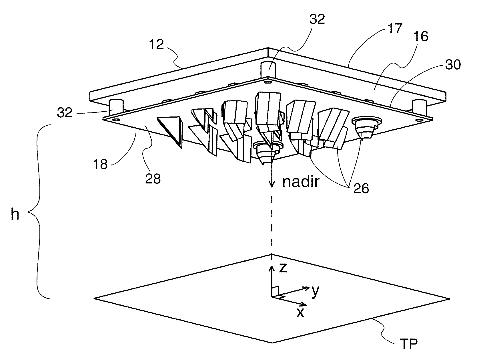
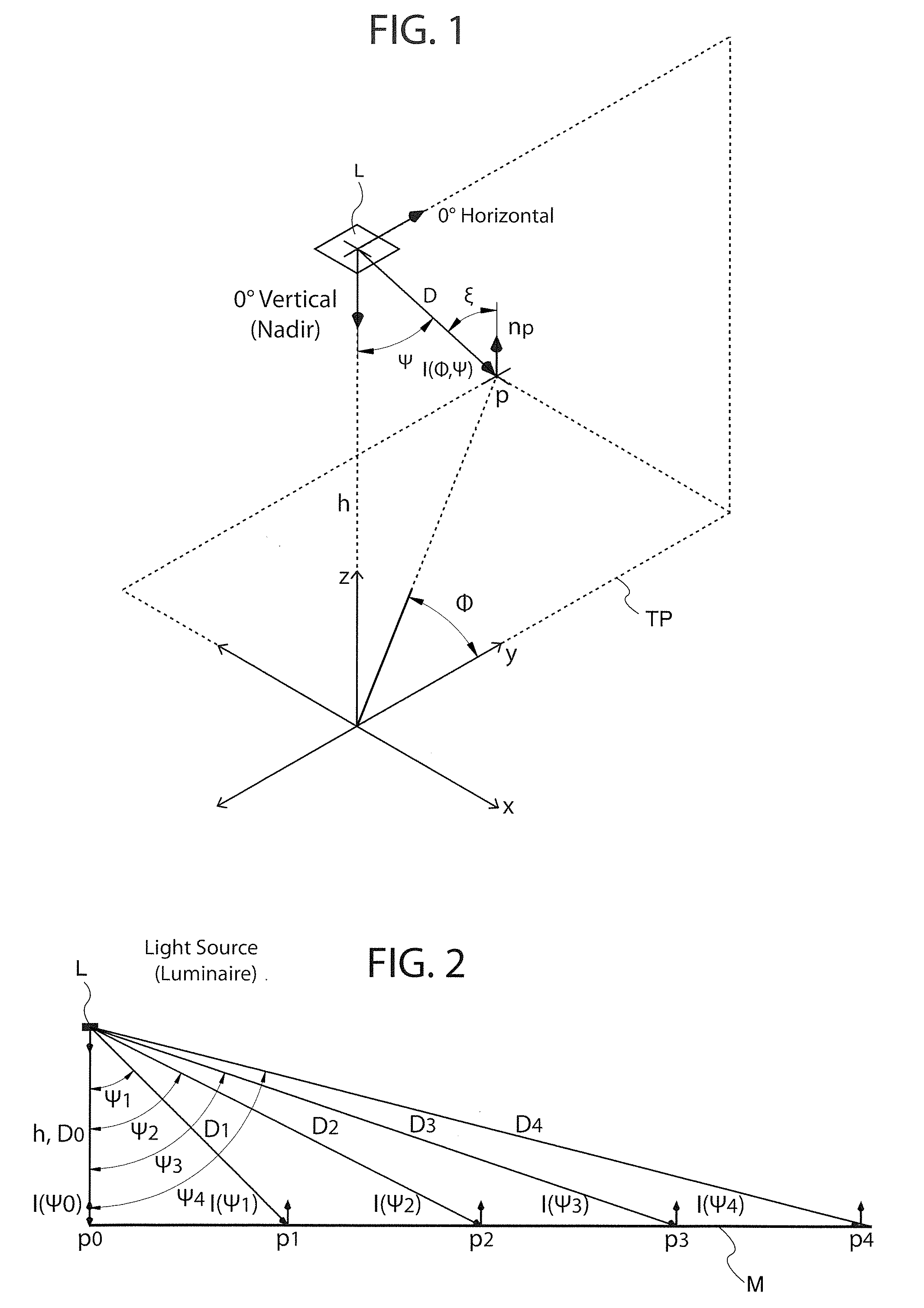
[0076]With reference to FIG. 1, the present invention aims to create a perfect intensity distribution by starting with the following equation for illuminance Ep at point P, where the point or location P is on target area or surface TP (x-y plane) illuminated by a light source or Luminaire L a distance h above (or away from the source) along z axis (or Nadir).

Ep=I(Φ,Ψ)*cos(ξ) / D2   Eqn (1)

[0077]where P=point or location on x-y plane

[0078]np=normal to point P on x-y plane

[0079]h=vertical distance along z axis from luminaire L to target (x-y) plane containing point P (in ft)

[0080]D=distance from luminaire to point P (in ft)

[0081]Φ=lateral angle from 0° Hz (y-axis) to point P (in ft)

[0082]Ψ=vertical angle from Nadir to point P (in ft)

[0083]I(Φ,Ψ)=intensity of luminaire L in direction of point P (in Candela or Cd)

[0084]ξ=angle between np and I(Φ,Ψ) or the incidence angle

[0085]Ep=Illuminance at point P (in Footcandles or FC)

[0086]For simplicity sake, it is assumed that the target plane TP ...


PUM


Abstract

An optical system for lighting fixtures uses light emitting diodes arranged in a 2-D array. In one embodiment, a lighting system comprises a framework carrying a plurality of diodes, where each diode has an associated optic that projects the light with a “high,”“medium” or “low” vertical throw, as provided by prismatic “teeth” that refract and reflect light rays in a predetermined manner so that the combined illumination patterns of each diode can blend to generally uniformly illuminate a target surface without dark spots or regions. Each optic has a common primary portion and a selected secondary portion whose tooth / teeth have a “swept” geometry for better angular (vertical and / or horizontal) control of light rays. Structural variations between different secondary portions reside in various factors, including plurality of teeth, length of the tooth along the longitudinal axis A, curvature(s) in the vertical and / or horizontal directions, and angularity or tightness of curvature of the swept geometry.

Description

CROSS-REFERENCE TO RELATED APPLICATIONS[0001]This application claims the benefit of U.S. Provisional Patent Application No. 61 / 234,248, Aug. 14, 2009, the entire disclosure of which is hereby incorporated by reference.FIELD OF INVENTION[0002]The present invention relates to lighting systems, in particular lighting systems using light emitting diodes to illuminate a target surface.BACKGROUND OF INVENTION[0003]A luminaire or light fixture includes at least a light source (or lamp), electrical components and a housing. A standard luminaire for illumination of surfaces, areas or objects typically uses a single light source and may include an optical arrangement to control raw light output from the single light source for more efficient distribution of the light. The optical arrangement can be a lens, a refractor, a reflector, or a combination of these optical elements that controls the light and produces a desired illumination pattern or distribution.[0004]Most standard lamps come in ve...

Claims


Application Information

Patent Timeline
Patent Type & Authority Applications(United States)
IPC IPC(8): F21V13/12
CPCF21S8/08F21V5/04F21Y2105/001F21Y2101/02F21W2131/103F21Y2105/10F21Y2115/10
Inventor CARRAHER, TIMOTHY J.PETERS, LUCAS C.
Owner U S POLE
Why Eureka
Try Eureka