Multi-Modal Drug Delivery System

a drug delivery and multi-modal technology, applied in the field of transdermal drug delivery devices and methods, can solve problems such as potential adverse effects on adjacent tissues and invading microorganisms

Active Publication Date: 2011-02-17
CAREWEAR CORP
View PDF38 Cites 174 Cited by
  • Summary
  • Abstract
  • Description
  • Claims
  • Application Information

AI Technical Summary

Benefits of technology

[0011]The present invention is directed to a device for the transdermal delivery of a therapeutic agent at a treatment site and methods of using the device. In general, the device comprises a housing containing a mechanical vibration element, a light source, a heating and / or cooling clement, a power source for powering the mechanical vibration clement, light source, and heating / cooling clement. An electronic control module is used to control the mechanical vibration element, light source, and heating and / or cooling element.

Problems solved by technology

The neutrophils that are stimulated begin to release proteases and reactive oxygen species into the surrounding medium with potential adverse effects on both the adjacent tissues and the invading microorganisms.

Method used


Image

  • Multi-Modal Drug Delivery System
  • Multi-Modal Drug Delivery System
  • Multi-Modal Drug Delivery System

Examples


first exemplary embodiment

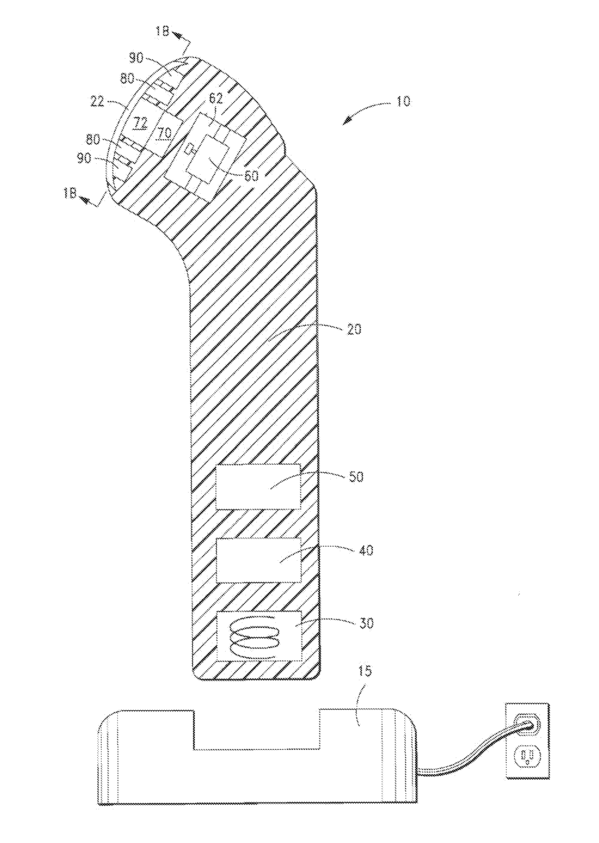
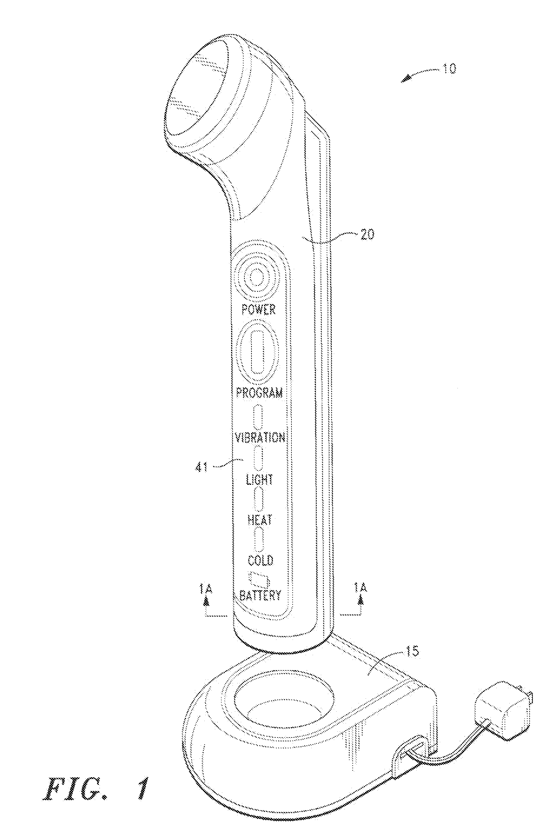
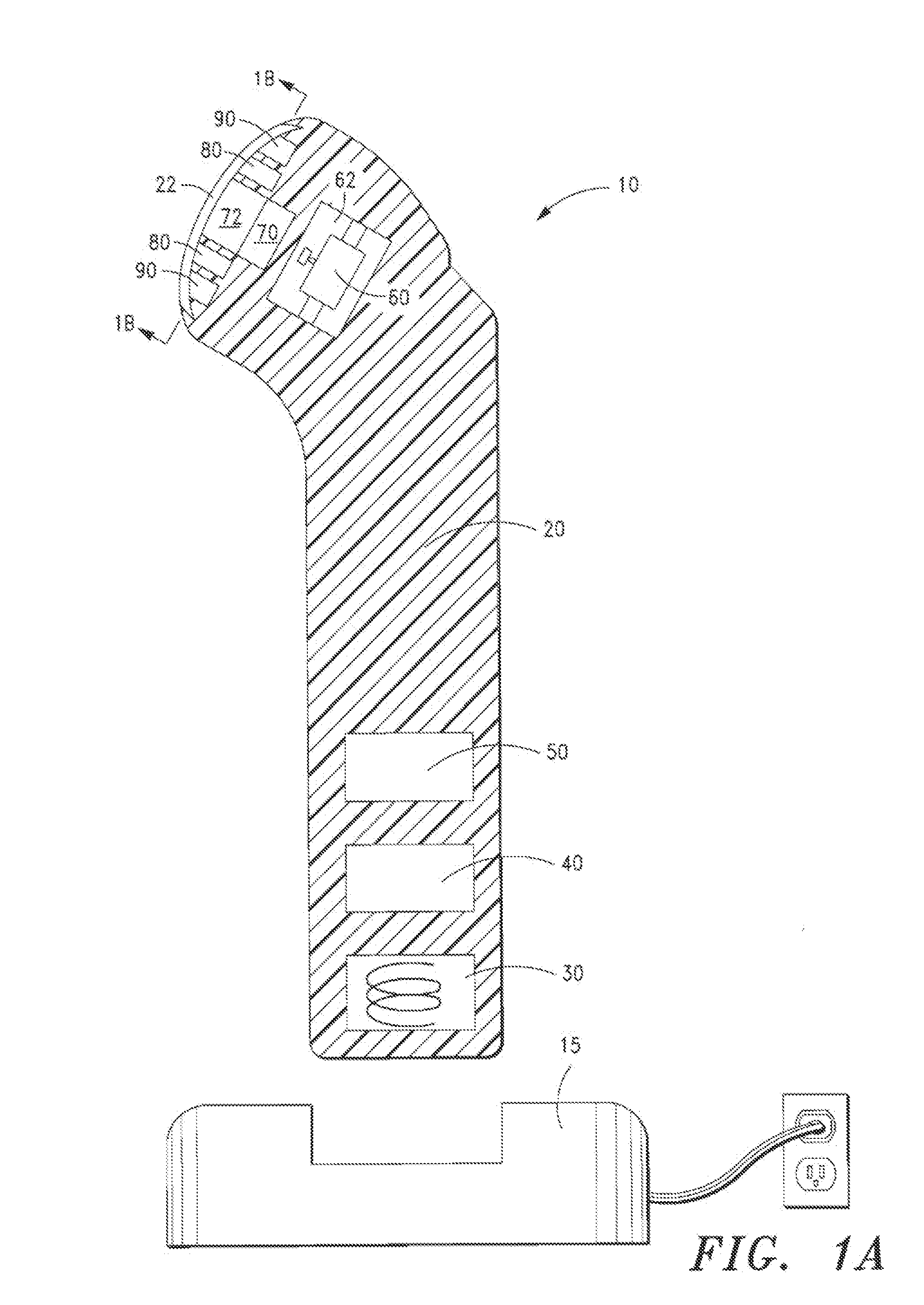
[0099]FIGS. 1, 1A and 1B illustrate a device 10 in accordance with a first embodiment of the present invention. The inventive device 10 comprises a housing 20 for containing the mechanical vibration, light energy, and heating / cooling elements. For simplicity, the elements arc shown in a block format. It will be appreciated to those skilled in the art that the device will be configured with the necessary wiring and circuits in order to permit the device to be operational as discussed herein.

[0100]As shown in FIG. 1 and FIG. 1A, the housing 20 is tubular or cylindrical in shape, and is comprised of injection-molded plastic. The housing is molded in so that the various components housed therein are positioned within cavities formed from the mold. A coil pick-up 30 together with an inductive battery charger 15, are used to charge the battery 50, which powers the electronic control module 40 and display panel 41 and other components in the device.

[0101]At one end of the device are the el...

second exemplary embodiment

[0105]FIGS. 2 and 2A illustrate a device 10 in accordance with a second embodiment of the present invention. The second embodiment is similar to the first embodiment except that the light energy from either the LEDs or the lasers is transmitted through a light pipe or light ring. Further, in the second embodiment, an ultrasonic transducer is used to generate the vibrational energy.

[0106]As with the first embodiment, the inventive device 10 comprises a housing 20 for containing the mechanical vibration, light energy, and optional heating / cooling elements. In this embodiment, an ultrasonic transducer 64 is used to deliver vibrational energy to the treatment site at a predetermined frequency. The electronic control module 40 is used to control the frequency of the transducer. Typically, the device is operated so that the vibrational frequency at the treatment site is between about 15 kHz and 35 kHz. As another example, the device is operated so that the vibrational frequency at the tre...

third exemplary embodiment

[0110]FIGS. 3 and 3A illustrate a device 10 in accordance with a third embodiment of the present invention. The third embodiment is similar to the second embodiment except that the light energy from the LEDs only is transmitted through a light pipe or light ring. Further, in the third embodiment, a scanning laser 70 is also used to deliver light to treatment site, and a buzzer 60 is used to generate the vibrational energy.

[0111]The inventive device 10 comprises a housing 20 for containing the mechanical vibration, light energy, and heating / cooling elements. The housing has an internal cavity 62 for holding an electric buzzer 60. The buzzer is mounted on the housing so that vibrational energy from the buzzer is transmitted through the housing to the treatment site at a predetermined frequency. The electronic control module 40 is used to control the frequency of the buzzer. Typically, the device is operated so that the vibrational frequency at the treatment site between about 10 Hz an...


PUM

PropertyMeasurementUnit
operating frequencyaaaaaaaaaa
frequencyaaaaaaaaaa

Abstract

A device for the transdermal delivery of a therapeutic agent at a treatment site comprising a housing containing: a mechanical vibration element; a light source; a heating and/or cooling clement; a power source for powering said mechanical vibrational element, light source, and heating element; and an electronic control module.

Description

CROSS-REFERENCE TO RELATED APPLICATIONS[0001]Not applicable.STATEMENT REGARDING FEDERALLY SPONSORED RESEARCH OR DEVELOPMENT[0002]Not applicable.BACKGROUND OF THE INVENTION[0003]1. Field of the Invention[0004]The present invention relates to transdermal drug delivery device and method, most preferably for the delivery of Vitamin C (ascorbic acid), using a combination of light therapy, heat therapy, cold therapy, and ultrasound therapy.[0005]2. Description of Related Art[0006]The process of wound healing generally encompasses three phases during which the injured tissue is repaired, regenerated, and new tissue is reorganized into a scar. These three phases arc classified as: (a) an inflammation phase which begins from about day 0 to 3 days, (b) a cellular proliferation phase from about 3 to 12 days, and (c) a remodeling phase from about 3 days to about 6 months. In all three phases, antioxidants, such as Vitamin C, play a vital role in the healing process.[0007]In the inflammation pha...

Claims


Application Information

Patent Timeline
Patent Type & Authority Applications(United States)
IPC IPC(8): A61M35/00B65D71/00
CPCA61F7/00A61N2005/067A61F2007/0087A61F2007/0096A61H7/005A61H23/0245A61H23/0263A61H2201/0228A61H2201/0285A61H2201/10A61H2201/105A61H2201/5038A61H2201/5082A61H2230/50A61M37/00A61M37/0092A61N2005/0644A61N2005/0651A61N2005/0659A61F2007/0075A61N5/0616A61N2005/0629A61N2005/063A61N2005/0652A61N5/067
Inventor CASTEL, J. CHRIS
Owner CAREWEAR CORP
Why Eureka
Try Eureka