Methods and Techniques for Creating and Visualizing Thermal Zones

Active Publication Date: 2011-02-17
GLOBALFOUNDRIES US INC
View PDF25 Cites 44 Cited by
  • Summary
  • Abstract
  • Description
  • Claims
  • Application Information

AI Technical Summary

Benefits of technology

[0004]The present invention provides techniques for using air flow distributions to model thermal zones. In one aspect of the invention, a method for modeling thermal zones in a space, e.g., in a data center, is provided. The method includes the following steps. A graphical representation of the space is provided. At least one domain is defined in the space for modeling. A mesh is created in the domain by sub-dividing the domain into a set of discrete sub-domains that interconnect a pl

Problems solved by technology

Energy consumption has become a critical issue for large scale computing facilities (or data centers), triggered by the rise in energy costs, supply and demand of energy and the proliferation of power hungry information and communication technology (ICT) equipment.
Although best practices have

Method used


Image

  • Methods and Techniques for Creating and Visualizing Thermal Zones
  • Methods and Techniques for Creating and Visualizing Thermal Zones
  • Methods and Techniques for Creating and Visualizing Thermal Zones

Examples


Embodiment Construction

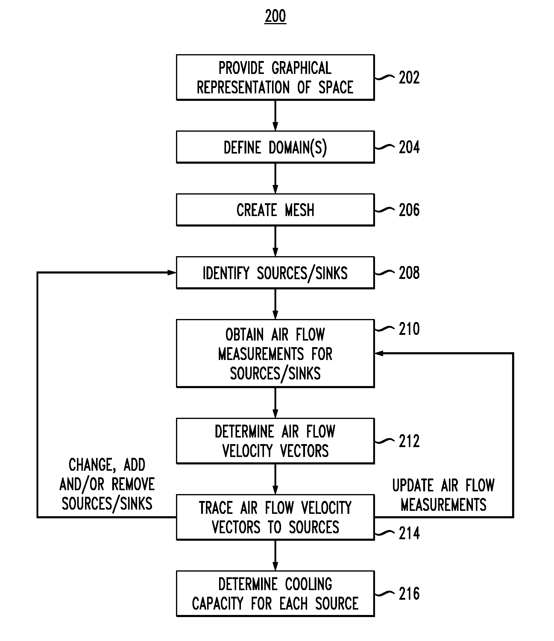
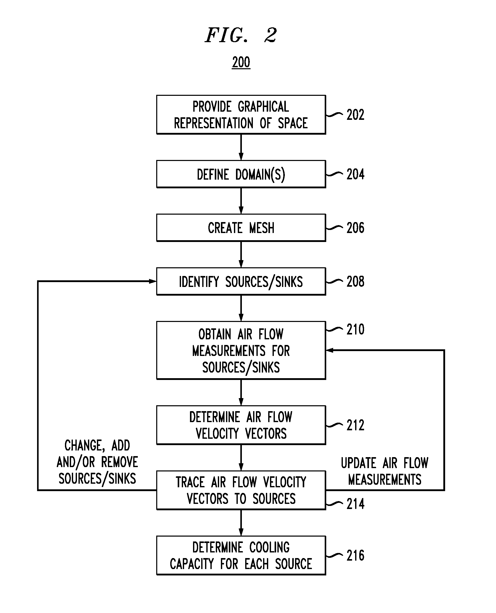
[0019]Presented herein are techniques for dynamically creating and visualizing thermal zones, which enables better provisioning and a more efficient usage of cooling for data centers. It is notable that while the instant techniques are described in the context of a cooling system of a data center, the concepts presented herein are generally applicable to cooling and / or heating systems in general.

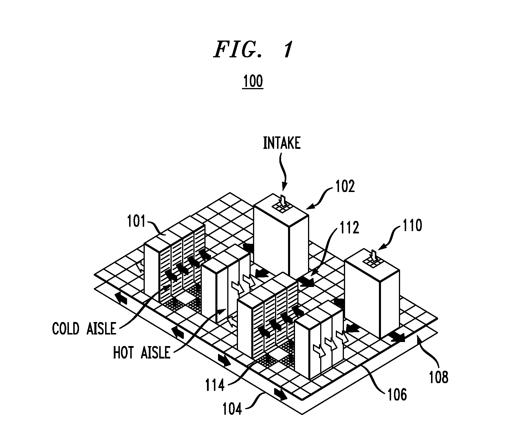
[0020]FIG. 1 is a diagram illustrating exemplary data center 100. Data center 100 has server racks 101 and a raised-floor cooling system with air conditioning units (ACUs) 102 (which may also be referred to as computer room air conditioners (CRACs)) that take hot air in (typically from above through one or more air returns in the ACUs) and exhaust cooled air into a sub-floor plenum below. Hot air flow through data center 100 is indicated by light arrows 110 and cooled air flow through data center 100 is indicated by dark arrows 112. In the following description, the data center above the sub...


PUM


Abstract

Techniques for using air flow analysis to model thermal zones are provided. In one aspect, a method for modeling thermal zones in a space, e.g., in a data center, includes the following steps. A graphical representation of the space is provided. At least one domain is defined in the space for modeling. A mesh is created in the domain by sub-dividing the domain into a set of discrete sub-domains that interconnect a plurality of nodes. Air flow sources and sinks are identified in the domain. Air flow measurements are obtained from one or more of the air flow sources and sinks. An air flow velocity vector at a center of each sub-domain is determined using the air flow measurements obtained from the air flow sources and sinks. Each velocity vector is traced to one of the air flow sources, wherein a combination of the traces to a given one of the air flow sources represents a thermal zone in the space.

Description

FIELD OF THE INVENTION[0001]The present invention relates to air flow analysis, and more particularly, to techniques for using air flow distributions to model thermal zones in a space, such as in a data center.BACKGROUND OF THE INVENTION[0002]Energy consumption has become a critical issue for large scale computing facilities (or data centers), triggered by the rise in energy costs, supply and demand of energy and the proliferation of power hungry information and communication technology (ICT) equipment. Data centers consume approximately two percent (%) of all electricity globally or 183 billion kilowatt (KW) hours of power; this power consumption is growing at a rate of 12% each year. A significant fraction of the power consumption, i.e., up to 50%, is directed to cooling the heat generating equipment. Consequently, the improvement of data center energy and cooling efficiency is very important. Although best practices have been widely publicized, data center operators are strugglin...

Claims


Application Information

Patent Timeline
IPC IPC(8): G06G7/56G06F17/50G06G7/57
CPCH05K7/20836G06F1/206G06F30/13
Inventor HAMANN, HENDRIK F.LOPEZ-MARRERO, VANESSASTEPANCHUK, ANDREW
Owner GLOBALFOUNDRIES US INC
Why Eureka
Try Eureka