PEM water electrolyser module
a technology pem water, which is applied in the direction of electrolysis components, instruments, optics, etc., can solve the problems of limited design and demonstration of limited attempts to design and demonstrate pem water electrolyser cell stacks, and limited active cell area and cell stacks, so as to maintain inherent scalability of the electrolyser module, reduce stress on the electrolyser module, and maintain the inherent s s
- Summary
- Abstract
- Description
- Claims
- Application Information
AI Technical Summary
Benefits of technology
Problems solved by technology
Method used
Image
Examples
example 1
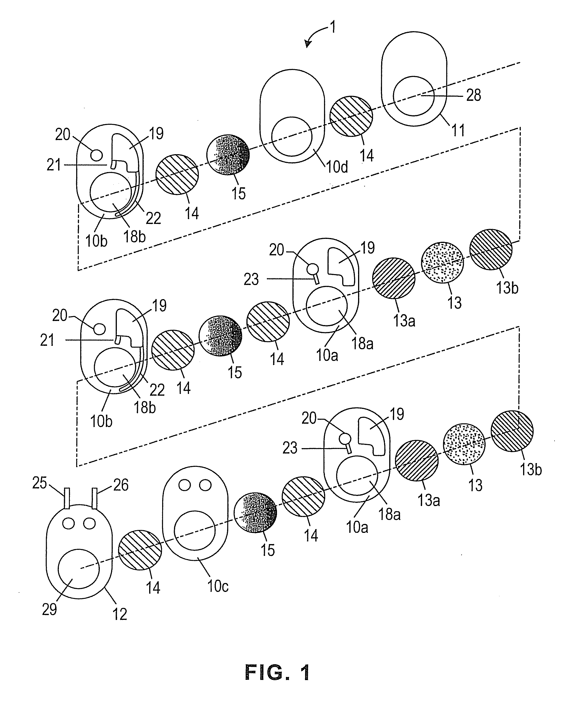
[0066]The fluid flows on the oxygen side of a six-cell PEM water electrolyser module according to the present invention were modeled by computational fluid dynamics (CFD). The general structural plate configuration was as shown in FIG. 3. The cell active area was 6,000 cm2. The hydrogen gas-liquid separation chamber was comprised of an upper section 30 cm×56.3 cm×13.2 cm. The cross sectional area of the gas-liquid passages and the degassed liquid passages was 3 cm2. The maximum current density investigated was 3,000 mA / cm2. This corresponds to a hydrogen generation rate per cathode half cell of 7.5 Nm3 / h. Simulations for current densities from 100 mA / cm2 to 3,000 mA / cm2 showed: (a) good oxygen gas-liquid separation efficiency, with negligible oxygen gas carry under to the half cell chamber; (b) high liquid circulation rates; and, (c) low void fractions at the top of the anode half cell chamber. The liquid circulation rates and void fractions for each of the six anode half cells were...
example 2
[0067]Next, the number of cells in the PEM water electrolyser module of Example 1 was increased to 50 cells. The fluid flows in the 50-cell electrolyser module were modeled by CFD. For simplicity, the fluid flows on the oxygen (anodes) side only are described herein. The results for each half cell were similar to those obtained for half cells in the six-cell electrolyser module, demonstrating the inherent scalability of the design. For example, fluid flow rates in any of the degassed liquid passages in the 50-cell electrolyser module were within 1% of fluid flow rates in any of the degassed liquid passages in the six-cell electrolyser module. Furthermore: (i) fluid flow rates in degassed liquid passages were higher in the 50-cell electrolyser module than in the six-cell electrolyser module, and (ii) the fluid flow rates in the degassed liquid passages for each of the 50 anode half cells were within 1% of each other. Similarly, void fractions at the tops of the 50 anode half cell cha...
example 3
[0068]Next, the number of cells in the PEM water electrolyser module of Example 2 was increased to 200 cells. The fluid flows in the 200-cell electrolyser module were modeled by CFD. For simplicity, the fluid flows on the oxygen (anodes) side only are described herein. The results for each half cell were similar to those obtained for half cells in six-cell and 50-cell electrolyser modules, demonstrating the inherent scalability of the design. For example, the range of fluid flow rates in the degassed liquid passages in the 200-cell electrolyser module was identical to the range of fluid flow rates in the degassed liquid passages in the 50-cell electrolyser module. Similarly, void fractions at the tops of the 200 anode half cell chambers were almost equal, and also were almost equal to the void fractions at the tops of the anode half cell chambers in the 50-cell electrolyser module.
PUM
| Property | Measurement | Unit |
|---|---|---|
| Length | aaaaa | aaaaa |
| Pressure | aaaaa | aaaaa |
Abstract
Description
Claims
Application Information
 - R&D
- Intellectual Property
- Life Sciences
- Materials
- Tech Scout
- Unparalleled Data Quality
- Higher Quality Content
- 60% Fewer Hallucinations
Browse by: Latest US Patents, China's latest patents, Technical Efficacy Thesaurus, Application Domain, Technology Topic, Popular Technical Reports.
© 2025 PatSnap. All rights reserved.Legal|Privacy policy|Modern Slavery Act Transparency Statement|Sitemap|About US| Contact US: help@patsnap.com


