
Light module, illumination system and method incorporating data in light emitted

a technology of illumination system and light module, which is applied in the direction of electric variable regulation, process and machine control, instruments, etc., can solve the problems of reducing the primary function of the system as an aid to human, the eye is very sensitive to intensity variations, etc., and achieves the effect of maximizing the detectability of a sensing device and minimizing the visibility of color coordinate modulation

Active Publication Date: 2011-02-24
KONINKLIJKE PHILIPS ELECTRONICS NV
View PDF7 Cites 39 Cited by
  • Summary
  • Abstract
  • Description
  • Claims
  • Application Information

AI Technical Summary

Benefits of technology

[0007]Based on the insight that the sensitivity of the human eye to changes in color is lower than to changes in intensity, the invention advantageously allows embedding the data into the light emitted from the illumination system without diminishing the performance of its primary function as an aid to human vision.
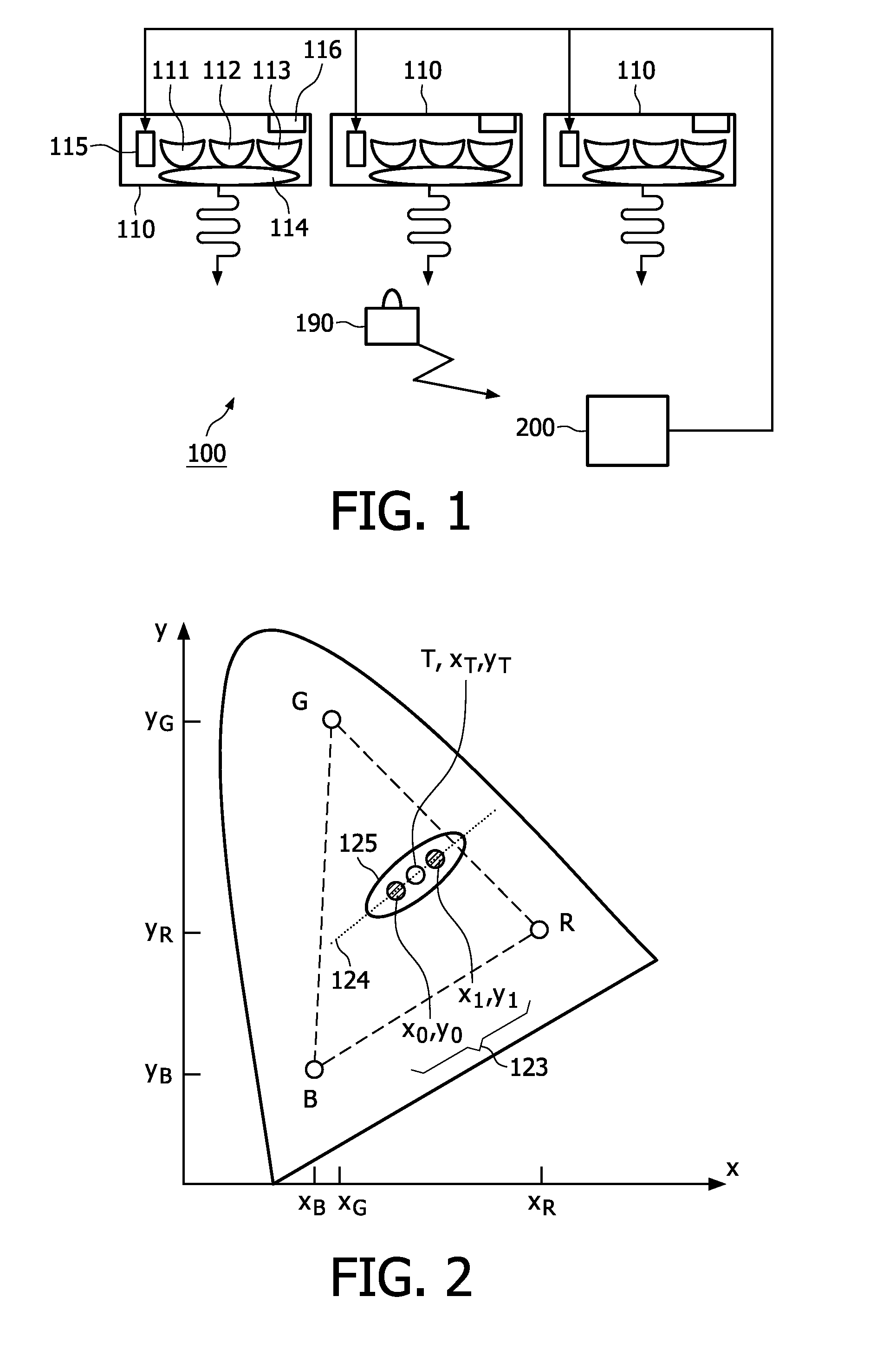
[0010]In an embodiment, the modulator is arranged to make use of a modulation alphabet, defining at least two chromaticity coordinates (x0,y0) and (x1,y1) representing at least a logical “0” and a logical “1”, for modulation of the color coordinates. In an embodiment, at least two of the chromaticity coordinates (x0,y0)and (x1,y1), of the modulation alphabet are arranged to lie on a common axis with the target chromaticity coordinate (xT,yT) of the light emitted. In yet another embodiment, the common axis forms the elongated axis of the MacAdam ellipse around a target chromaticity coordinate (xT,yT) of the light emitted. Advantageously, this arrangement minimizes the visibility of the color coordinate modulation for an observer, while simultaneously it maximizes the detectability for a sensing device.
[0011]In an embodiment, the least two chromaticity coordinates (x0,y0) and (x1,y1) represent a predetermined color shift Δxy0 and Δxy1, respectively. This embodiment has considerable advantage when embedding data using a modulation in a more homogeneous non-distorted reference color space, such as the CIE L*a*b* and CIE Luv spaces.

Problems solved by technology

A drawback of the solution described in US2007 / 0008258 is that the human eye is very sensitive for intensity variations, in particular in certain frequencies ranges.
Thus, the secondary use of an illumination system as part of a communication network by implementing data in the light emitted as intensity variations may diminish the primary function of the system as an aid to human vision, especially when used in the high sensitivity frequency ranges of the human eye.

Method used


Image

  • Light module, illumination system and method incorporating data in light emitted
  • Light module, illumination system and method incorporating data in light emitted
  • Light module, illumination system and method incorporating data in light emitted

Examples


Embodiment Construction

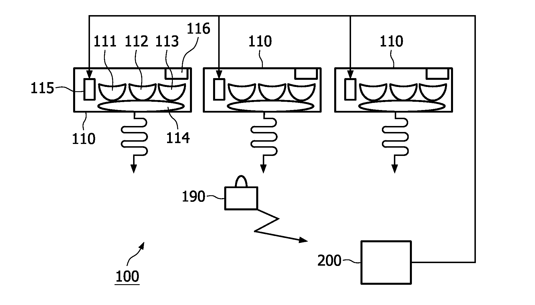
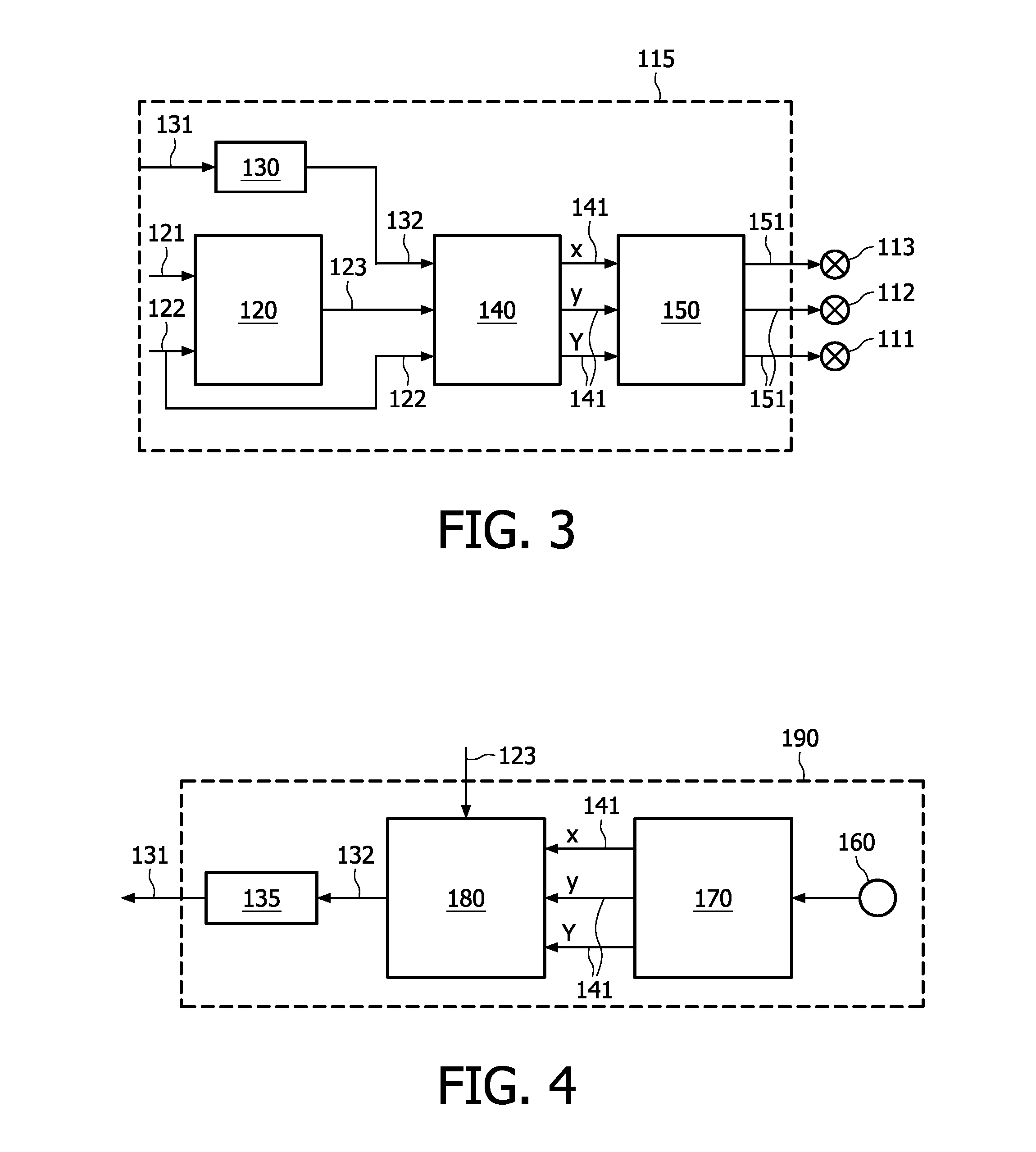
[0020]FIG. 1 shows an illumination system 100 according to the invention. The system comprises a plurality of light modules 110. Each module comprises at least two primary light sources 111,112,113 capable of emitting a primary color light enabling the light module to emit combined light having intensity (Y) and color coordinates (xy) through mixing the primary color light emitted by the light sources using appropriate mixing optics 114. The light sources can in principle be of any type, such as gas discharge bulbs, inorganic light emitting diodes (LEDs), organic LEDs, and laser diodes. Thus, as an example a light module 110 may comprise three primary color light sources 111,112,113 emitting red, green, and blue light, respectively. Alternatively, the light modules might comprise more than three light sources, such as a fourth amber LED. Alternatively yet, the light modules 110 may even comprise a (fifth) phosphor-coated LED emitting a broadband predefined spectrum such as white lig...


PUM


Abstract

Proposed is a light module (110) comprising at least two primary light sources (111,112,113) capable of emitting a primary color light. This allows the light module to emit light having intensity (Y) and color coordinates (x,y) through additive color mixing of the constituent primary colors. The light module further comprises an modulator (115) capable of modulating the primary light sources enabling embedment of data in the light emitted. The modulator (115) is arranged to modulate the color coordinates of the light emitted for embedding the data. This is especially advantageous as the sensitivity of the human eye to changes in color is lower than to changes in intensity. The invention thus advantageously allows embedding the data into the light emitted from the light modules (110) of an illumination system (100) without reducing the performance of its primary function as an aid to human vision.

Description

FIELD OF THE INVENTION[0001]The invention relates to a light module comprising at least two primary light sources capable of emitting a primary color light enabling the light module to emit light having intensity (Y) and color coordinates (x,y), the light module further comprising a modulator capable of modulating the primary light sources enabling embedment of data in the light emitted. Furthermore, the invention relates to an illumination system comprising such light modules. Moreover the invention relates to a method of embedding data in light emitted by the light modules. Such devices in particular are of interest in advanced control of illumination systems and free space transmission of data in confined spaces.BACKGROUND OF THE INVENTION[0002]An embodiment of an illumination system of the kind set forth is known from US2007 / 0008258. That document discloses an illumination based communication network making use of free space transmission of data incorporated in the light emitted...

Claims


Application Information

Patent Timeline
Patent Type & Authority Applications(United States)
IPC IPC(8): H04B10/04H04B1/69H04B10/114H04B10/116
CPCH05B37/02H04B10/116H04B10/114H05B37/0272H05B47/10H05B47/19
Inventor SCHENK, TIM CORNEEL WILHELMUSFERI, LORENZODAMINK, PAULUS HENRICUS ANTONIUSVERNHOUT, MARTIN MAURICESEKULOVSKI, DRAGAN
Owner KONINKLIJKE PHILIPS ELECTRONICS NV
Learn More