Fusing core and drive collar assembly

a drive collar and core technology, applied in the field of products and methods, can solve the problems of failure modes of the apparatus, deformation of print media, or other undesirable consequences, and achieve the effect of reducing the wear of micro machining

Inactive Publication Date: 2011-02-24
7 SIGMA
View PDF11 Cites 3 Cited by
  • Summary
  • Abstract
  • Description
  • Claims
  • Application Information

AI Technical Summary

Benefits of technology

Yet another objective of the present invention is to further reduce the micro machining wear issues between contacting surfaces.
Another objective of the present invention is to provide an apparatus which eliminates the need for a drive member

Problems solved by technology

Uneven or non-uniform pressure may result in degraded print quality, wrinkled print media, or other undesirable consequences.
As the imaging device rotates at operating revolutions, instabilities are created by extremely fast stop/start conditions, causing micro machining issues between the contacting surfaces, which eventually develop failure modes of the apparatus.
The differences in thermal expansion between the various components adverse

Method used


Image

  • Fusing core and drive collar assembly
  • Fusing core and drive collar assembly
  • Fusing core and drive collar assembly

Examples


Embodiment Construction

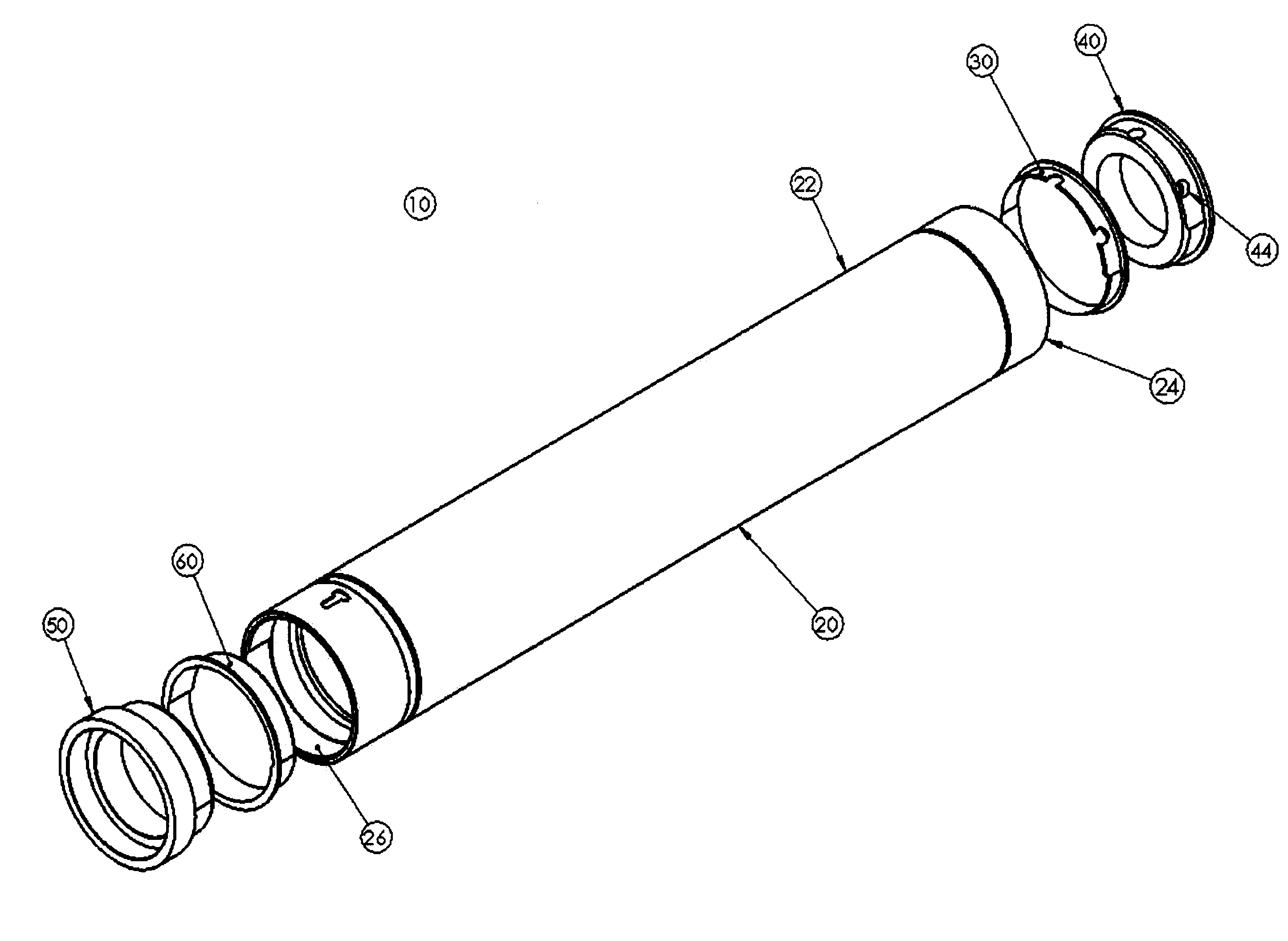
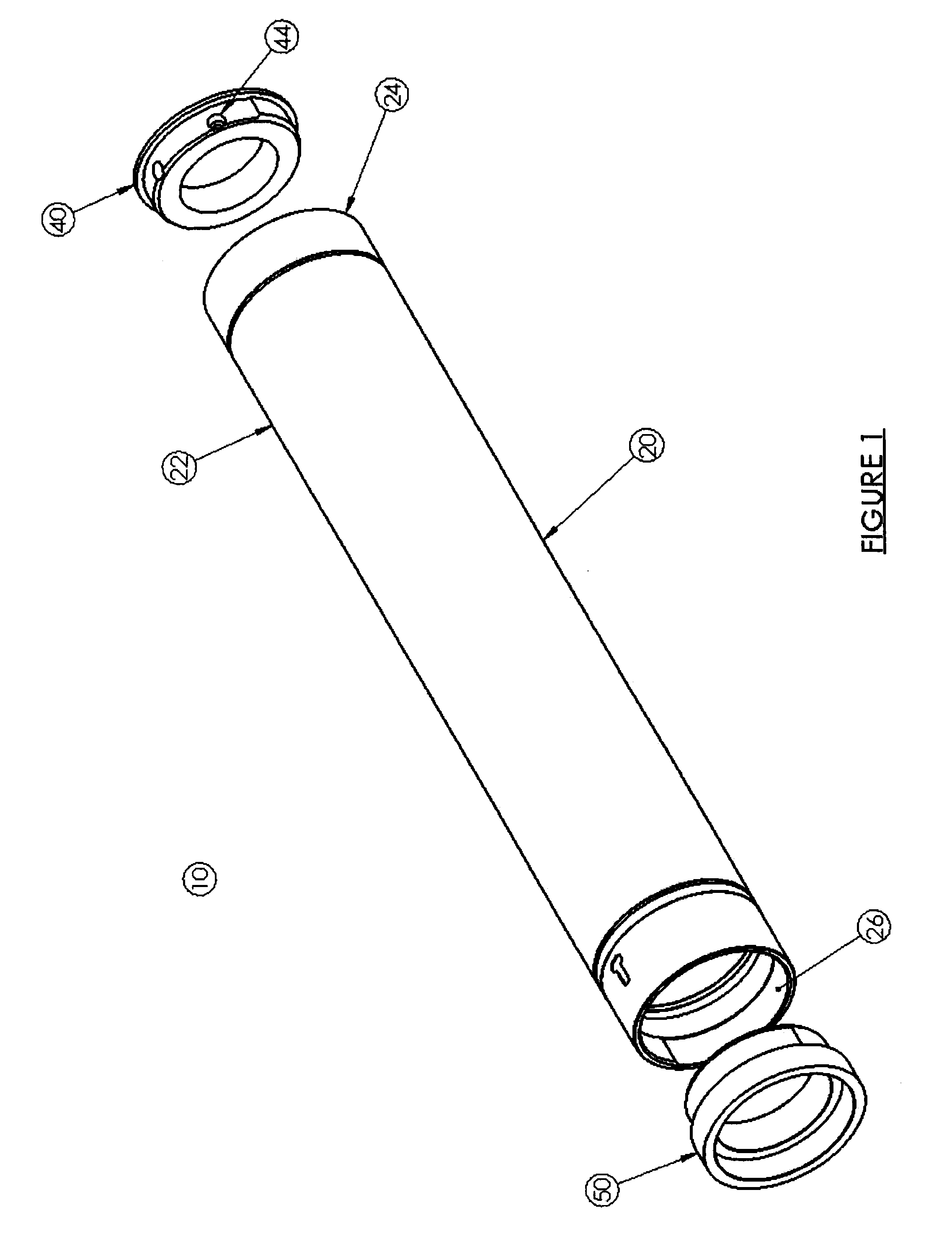
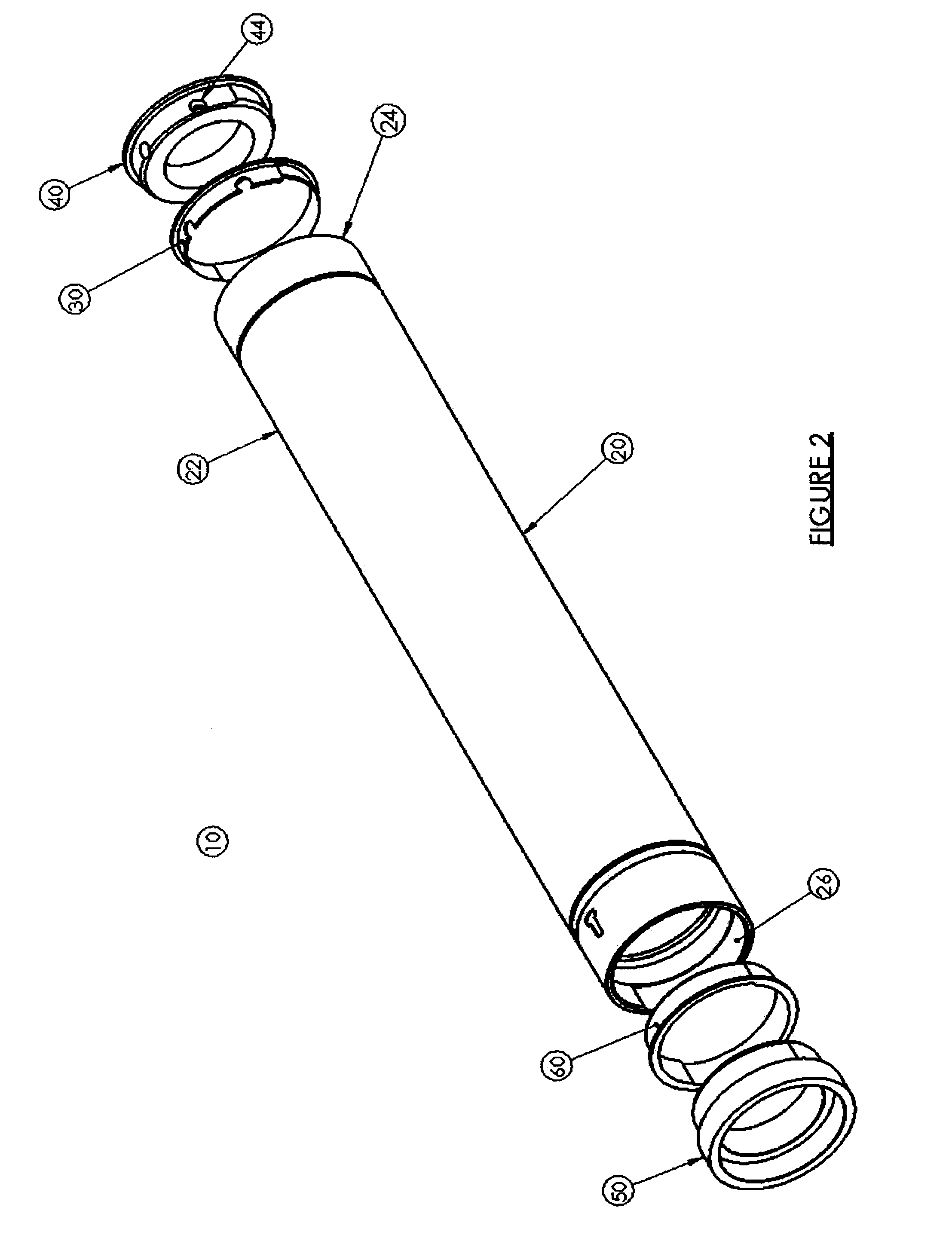
With reference to FIGS. 1-2, a fuser assembly 10 of the present invention is shown. Assembly 10 includes a fuser core 20, a first collar 30, a first hub 40, a second collar 40, and a second hub 50. Fuser core 20 defines an elongated shaft 22 terminating at a first end 24 and a second end 26. Fuser core 20 is typically fabricated from aluminum or another material suitable for transferring heat.

Fuser core 20 mates with hub 40 at end 24 and hub 50 at end 26, respectively, to facilitate rotation of core 20. The specific configuration of hub 40, hub 50 and core 20 will vary depending upon the specific printer or copier in which it is used. Hub 40 may also include aperture 44 to mount hub 40 to an electrophotographic printer or copier. Hub 50 is shown having an exterior ratchet type geometric surface profile with two arcs. Core end 26 is show having a mating interior ratchet type geometric surface profile with two arcs. FIG. 3 shows an expanded isometric view of core 20 with an end 26 hav...


PUM


Abstract

A system for stabilizing a fuser core in an imaging device. The system includes a fuser core having a body and two opposing ends, and a pair of hubs. The opposing ends of the fuser core are configured with ratchet type geometric profiles that mate with ratchet type geometric profiles configured on the corresponding hubs. The system also includes two elastomeric collars each of which is at least partially disposed between the end of the fuser core and the corresponding mating hub.

Description

FIELD OF THE INVENTION The present invention generally relates to products and methods for fusing toner to print media. More particularly, the invention relates to a self locking drive mechanism apparatus for minimizing the wear on the core and hub assembly and minimizing the gap caused by thermal expansion of the fusing system members at operating temperature.BACKGROUND OF THE INVENTION Laser printers and other electrophotographic image forming devices use toner particles to form a desired image on print media. The print media is often paper, although a wide variety of different print media may be employed. Once the toner is applied to the media, the media is advanced along a media path to a thermal fuser. In some image forming devices, the fuser includes a fuser roller and a mating pressure roller. As the media passes between the fuser roller and the pressure roller, the toner is fused to the media through a process using pressure and heat exceeding 300.degree. F. (148.degree. C.)...

Claims


Application Information

Patent Timeline
IPC IPC(8): G03G15/20
CPCG03G2215/2058G03G15/2053
Inventor DUDA, RICHARD MEICHHORN, WADE RWYROBEK, KRISTIAN G
Owner 7 SIGMA
Why Eureka
Try Eureka