Methods and systems for turbocharger control

a turbocharger and boost technology, applied in the direction of electric control, machine/engine, vehicle sub-unit features, etc., can solve the problems of reducing vehicle performance, reducing engine speed, and consequently turbocharger boost, etc., to achieve good driveability, reduce engine speed, and increase aircharge

Active Publication Date: 2011-02-24
FORD GLOBAL TECH LLC
View PDF7 Cites 58 Cited by
  • Summary
  • Abstract
  • Description
  • Claims
  • Application Information

AI Technical Summary

Benefits of technology

[0002]Vehicles may be configured with transmissions wherein gears are automatically shifted responsive to vehicle operating conditions. During gear upshifts, engine speed is reduced. Then, following the upshift, the engine speed is returned to an increased level. To provide good driveability, following the gear upshift, power losses to the wheels (due to the engine speed reduction), may be compensated for by providing more engine

Problems solved by technology

However, due to turbocharger inertia, the turbocharger speed, and consequently turbocharger boost, desired during and following the upshift is delayed with respect to the engine speed change.
As such, this turbo lag results in the feeling of a poor and slow shift, and reduces vehicle performance.
However, the inventors have recognized several potential issues with such a method.

Method used


Image

  • Methods and systems for turbocharger control
  • Methods and systems for turbocharger control
  • Methods and systems for turbocharger control

Examples


Embodiment Construction

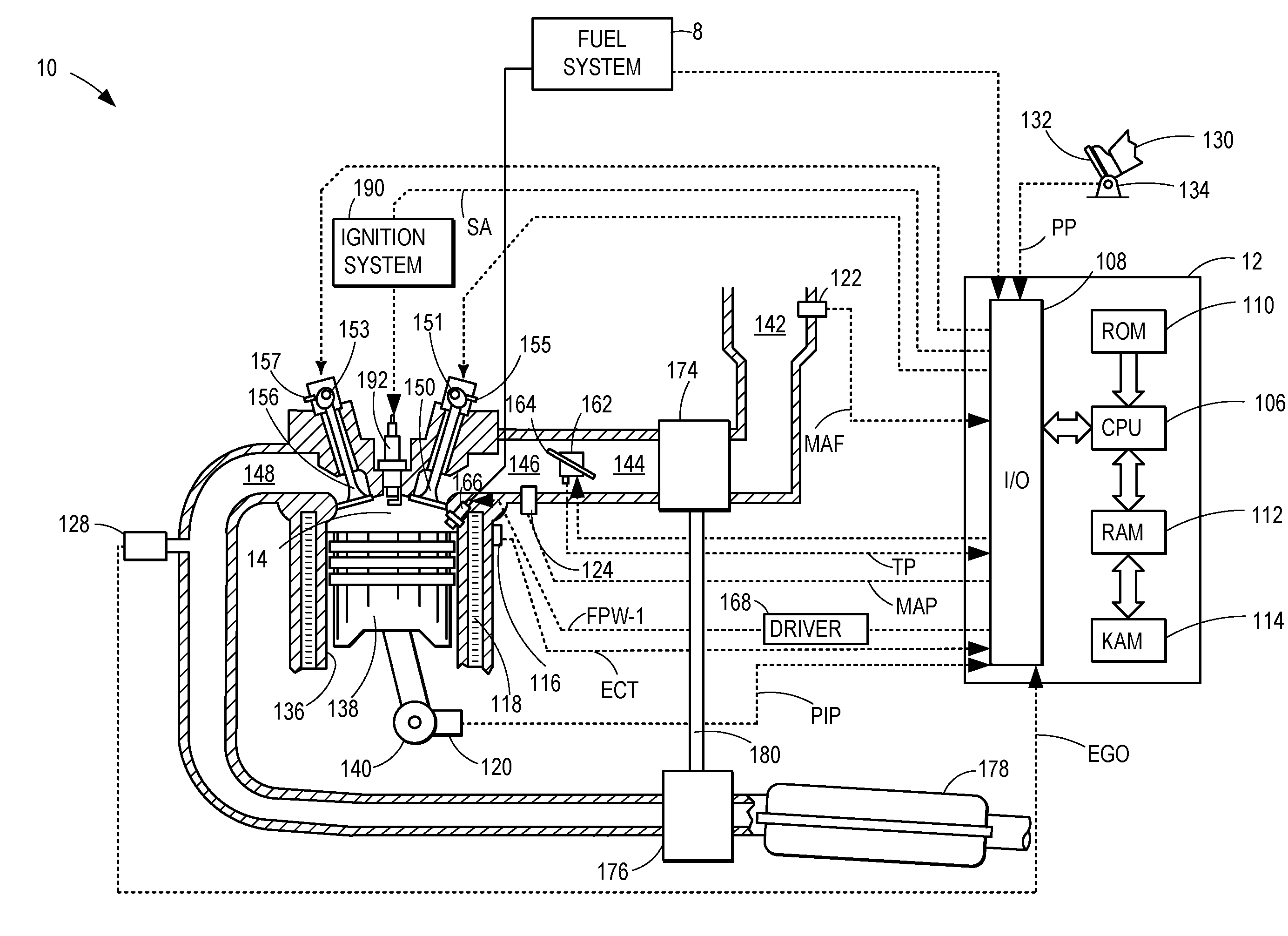
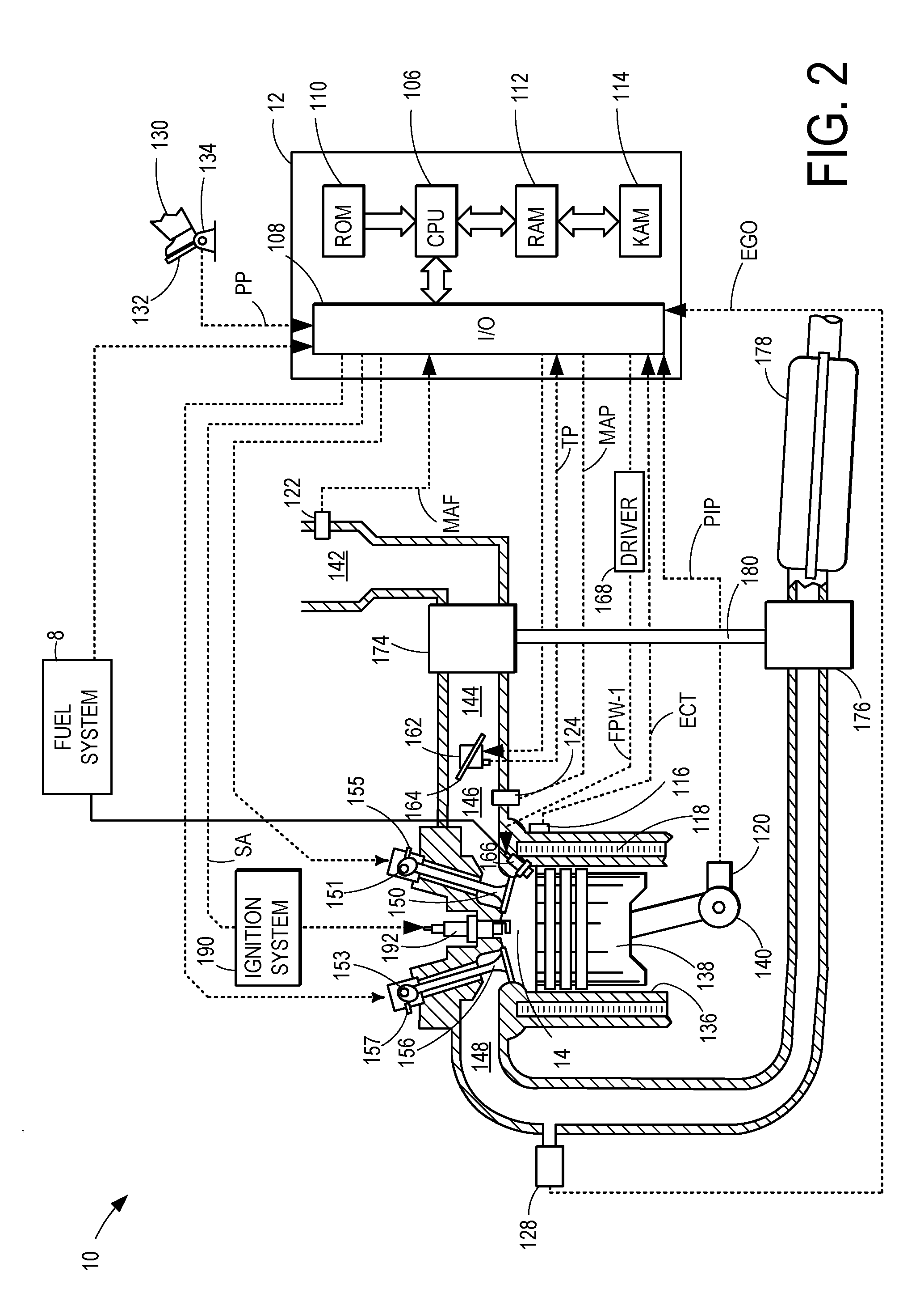
[0012]The following description relates to systems and methods for adjusting engine operation during transmission gear shifts. Specifically, the method enables potential torque differences, arising due to engine speed changes during and / or after the gear shift, to be compensated for using a turbocharger. An engine controller may be configured to perform a control routine, such as the routine depicted in FIG. 3, following the prediction of an upcoming gear shift, to adjust the settings and schedule of a turbocharger boost during the gear shift. The turbocharger settings may be adjusted to match a predicted boost profile. As illustrated in FIG. 4, the turbocharger adjustments may be initiated before the gear shift commences and may continue during a transition period before the gear shift is completed. Further torque adjustments may be achieved by modulating the throttle. That is, the turbocharger settings may be adjusted to preposition the boost in anticipation of a desired boost lev...


PUM


Abstract

Methods and systems are provided for controlling a vehicle engine, the engine including a turbocharger and a transmission. One example method comprises, operating the transmission at a first lower gear with a first boost level, increasing the boost from the first boost level before completing a shift from the first lower gear to a second higher gear, and after completing the shift, operating the transmission at the second higher gear with the increased boost.

Description

FIELD[0001]The present application relates to methods and systems for controlling the turbocharger boost, specifically during gear shifts.BACKGROUND AND SUMMARY[0002]Vehicles may be configured with transmissions wherein gears are automatically shifted responsive to vehicle operating conditions. During gear upshifts, engine speed is reduced. Then, following the upshift, the engine speed is returned to an increased level. To provide good driveability, following the gear upshift, power losses to the wheels (due to the engine speed reduction), may be compensated for by providing more engine torque. Vehicle engines may use boosting devices, such as turbochargers, to provide more aircharge and achieve increased engine torque. However, due to turbocharger inertia, the turbocharger speed, and consequently turbocharger boost, desired during and following the upshift is delayed with respect to the engine speed change. As such, this turbo lag results in the feeling of a poor and slow shift, an...

Claims


Application Information

Patent Timeline
IPC IPC(8): B60W10/04F02D23/00
CPCB60W10/06B60W10/11B60W30/1882F02B37/00F02D23/02F02D41/0007Y10T477/55F02D2200/0406F02D2250/21Y02T10/144B60Y2400/435Y10T477/50F02D41/023F02D2250/22Y02T10/12
Inventor DOERING, JEFFREY ALLENROLLINGER, JOHN ERICCHEN, DE-SHIOUBUCKLAND, JULIA HELENWAIT, SUZANNE KAYGERHART, MATTHEW JOHNKUECHLER, PETER DOUGLAS
Owner FORD GLOBAL TECH LLC
Why Eureka
Try Eureka