Optical disk drive

a technology of optical disk drive and optical drive, which is applied in the field of optical disk drive, can solve the problems of erroneous data being read from or written to the disk, and achieve the effect of improving the accuracy of data

Inactive Publication Date: 2011-02-24
HON HAI PRECISION IND CO LTD
View PDF12 Cites 0 Cited by
  • Summary
  • Abstract
  • Description
  • Claims
  • Application Information

AI Technical Summary

Benefits of technology

[0004]An optical disk drive usually includes a main body and a tray slidably coupled to the main body. The main body includes two rails for allowing the tray to slide therein. To decrease resistance between the tray and the rails when the tray is sliding in or out, the tray is usually spaced a distance away from the rails. Thus, when the optical disk drive reads or writes to a spinning optical disk, the vibration of the tray caused by the play between the tray and the rails may lead to erroneous data being read from or written to the disk.

Problems solved by technology

Thus, when the optical disk drive reads or writes to a spinning optical disk, the vibration of the tray caused by the play between the tray and the rails may lead to erroneous data being read from or written to the disk.

Method used


Image

  • Optical disk drive
  • Optical disk drive
  • Optical disk drive

Examples


Embodiment Construction

[0013]Embodiments of the present disclosure will now be described in detail with reference to the drawings.

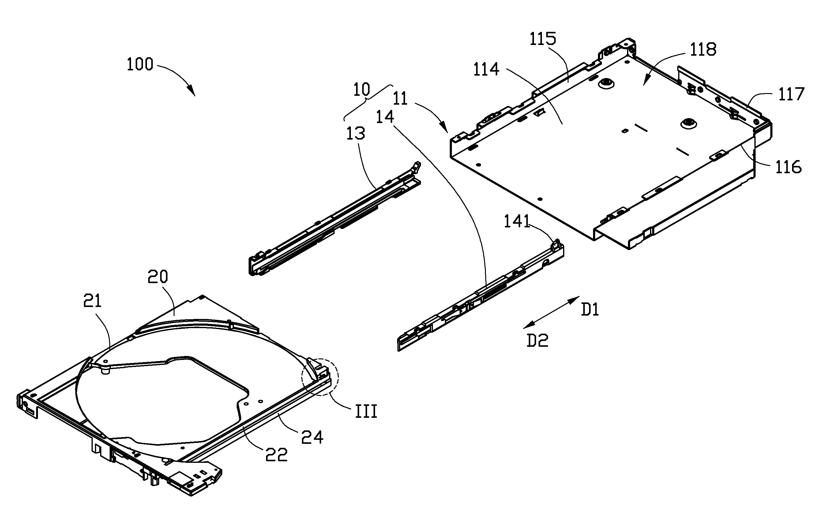
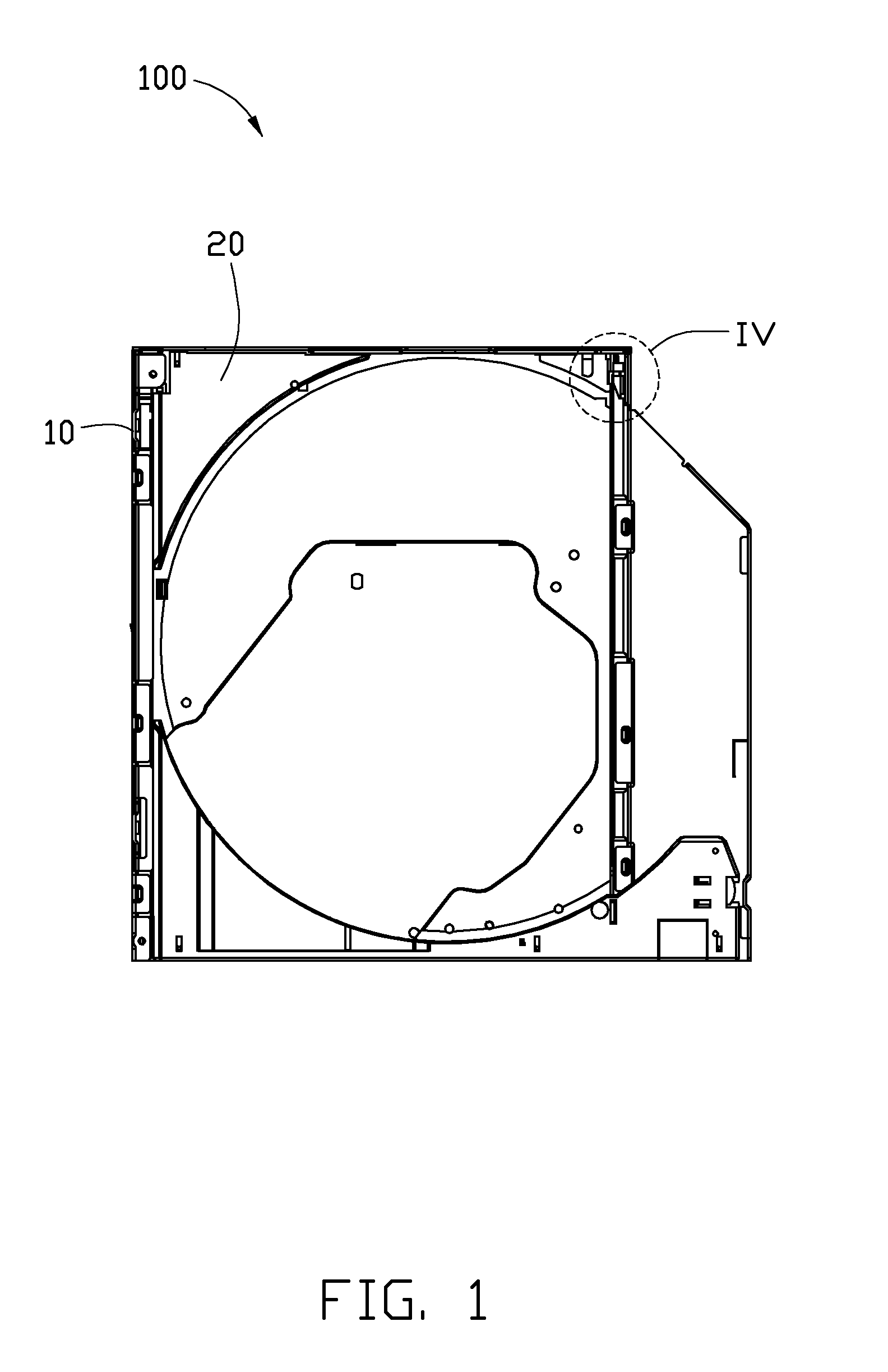
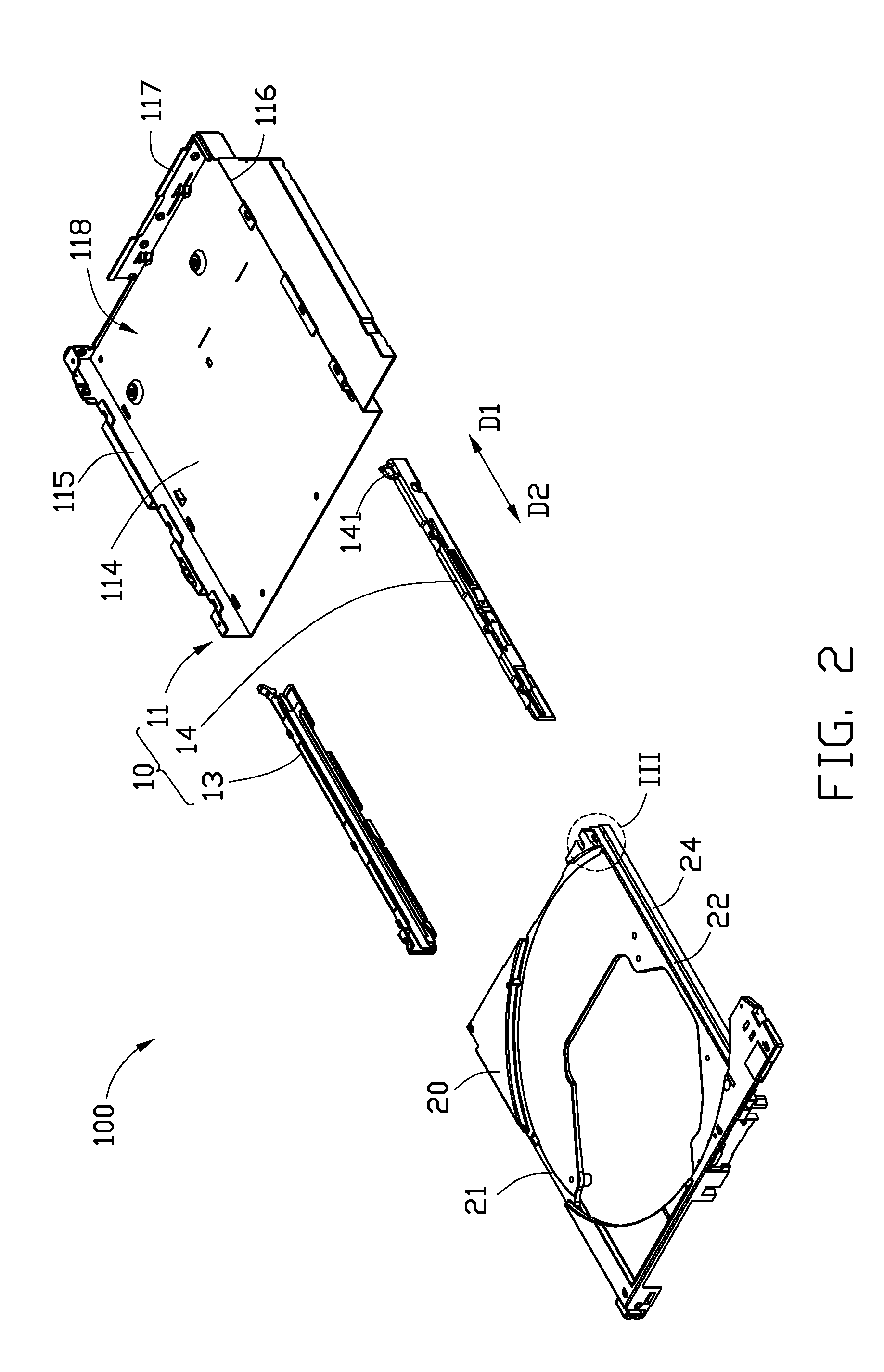
[0014]Referring to FIGS. 1 and 2, an optical disk drive (ODD) 100 in accordance with an exemplary embodiment is illustrated. In the embodiment, the optical disk drive 100 may be a slim type version, particularly employed in a laptop computer (not shown). The ODD 100 includes a main body 10 and a tray 20 slidably coupled to the main body 10. The tray 20 is adapted to receive an optical disk (not shown). When the tray 20 is completely received in the main body 10, the disk drive 100 is operable to drive the optical disk.

[0015]The main body 10 includes a housing 11, a first rail 13, and a second rail 14. The housing 11 includes a bottom plate 114 and three sidewalls 115, 116, 117 extending upright from three edges of the bottom plate 114 respectively. The sidewall 115 is substantially parallel to the sidewall 116. The sidewall 117 is substantially perpendicularly connected between...


PUM

PropertyMeasurementUnit
resisting forceaaaaaaaaaa
resistanceaaaaaaaaaa
acute angleaaaaaaaaaa

Abstract

An optical disk drive includes a main body and a tray. The main body includes a housing and two rails disposed in the housing. The tray is slidably coupled to the two rails, and is operable to be switched between a first state and a second state. The tray is received in the housing in the first state, and protrudes out of the housing in the second state. The main body further includes a first resisting member. The tray includes a second resisting member. The first resisting member is adapted to apply a resisting force to the second resisting member in the first state to secure the tray. The first resisting member is away from the second resisting member in the second state.

Description

BACKGROUND[0001]1. Technical Field[0002]The present disclosure relates to optical pick-up devices, and particularly to an optical disk drive capable of tightly securing a tray.[0003]2. Description of Related Art[0004]An optical disk drive usually includes a main body and a tray slidably coupled to the main body. The main body includes two rails for allowing the tray to slide therein. To decrease resistance between the tray and the rails when the tray is sliding in or out, the tray is usually spaced a distance away from the rails. Thus, when the optical disk drive reads or writes to a spinning optical disk, the vibration of the tray caused by the play between the tray and the rails may lead to erroneous data being read from or written to the disk.[0005]Therefore, it is desirable to provide an optical disk drive capable of tightly securing a tray, which can overcome the above-mentioned problems.BRIEF DESCRIPTION OF THE FIGURE[0006]The components of the drawings are not necessarily dra...

Claims


Application Information

Patent Timeline
Patent Type & Authority Applications(United States)
IPC IPC(8): G11B17/04
CPCG11B17/056
Inventor CHANG, TENG-YUAN
Owner HON HAI PRECISION IND CO LTD
Why Eureka
Try Eureka