Seismic Horizon Skeletonization

a seismic horizon and skeletonization technology, applied in the field of seismic data analysis, can solve the problems of short successful paths, no topology or topological consistency, and no reference discloses the creation of surfaces, etc., to reduce storage or computational efficiency requirements

Inactive Publication Date: 2011-03-03
IMHOF MATTHIAS G +6
View PDF25 Cites 72 Cited by
  • Summary
  • Abstract
  • Description
  • Claims
  • Application Information

AI Technical Summary

Benefits of technology

[0030]Further still, one or more embodiments of the method may include wherein merging neighboring patches in a topologically consistent way is performed by developing overlap and neighbor tables for the patches, generating an order for merge pair candidates by sorting the overlap and neighbor tables, checking candidate merges for topological consistency using the overlap and neighbor tables, and accepting topologically consistent mergers; wherein the sort order of the neighbor table is based on geometries of, or geometry differences between, the neighboring patches, or is based on the statistical properties of, or the differences between, one or more attributes extracted from seismic data collocated with the patches; wherein only unique correlations are accepted; identifying and also accepting multiply correlated connections characterized by two or more correlations from a single peak, trough or zero crossing all exceeding the threshold; spatially flattening the topologically consistent reflection-based surfaces into an order representing the sequence of deposition using the topologically consistent reflection-based surfaces and using the flattened surfaces to predict or analyze potential for hydrocarbon accumulations; flattening the associated seismic data within which the topologically consistent reflection-based surfaces exist; wherein the seismic data flattening is performed by nonlinear stretch of the seismic data or by a cut and past method; wherein e

Problems solved by technology

Most of these methods create surfaces that eventually overlap themselves.
Ants follow each other's scent, and over time, short successful paths emer

Method used


Image

  • Seismic Horizon Skeletonization
  • Seismic Horizon Skeletonization
  • Seismic Horizon Skeletonization

Examples


Embodiment Construction

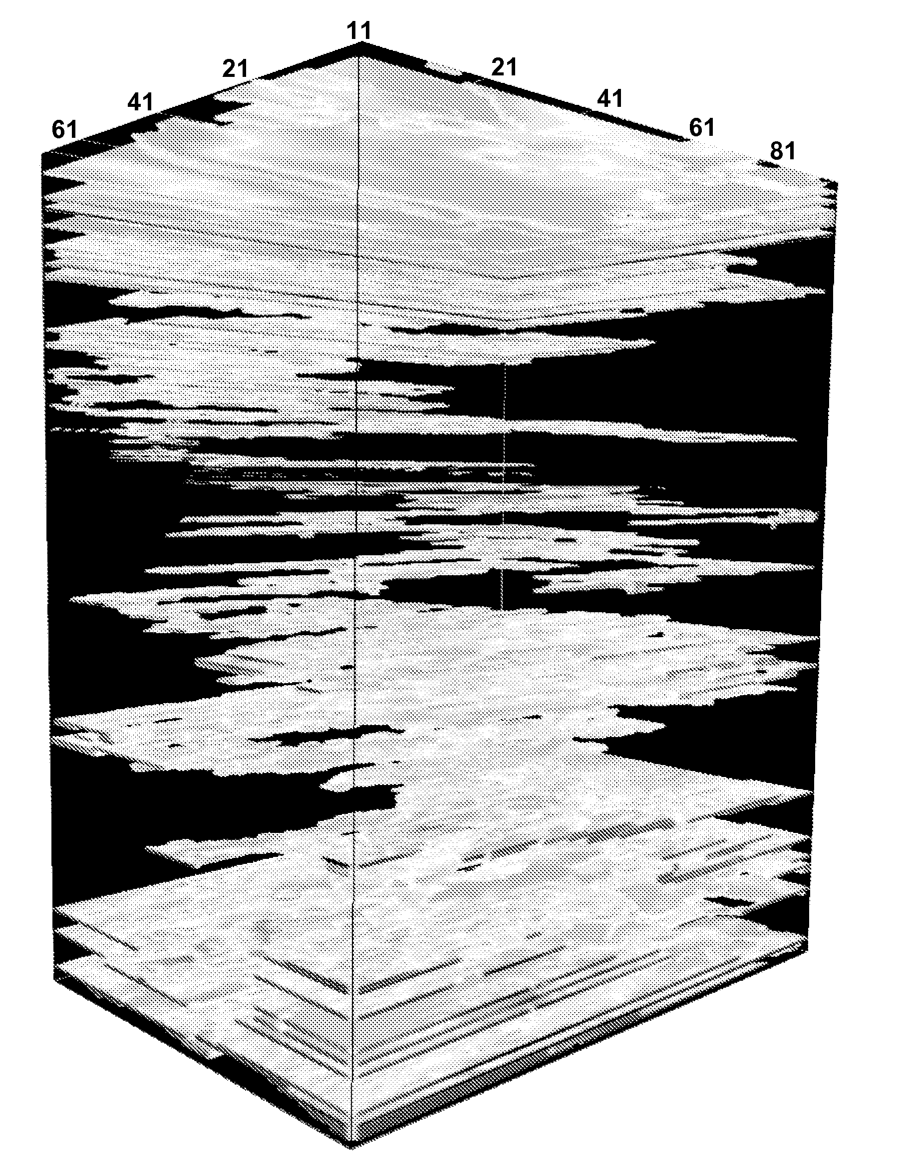
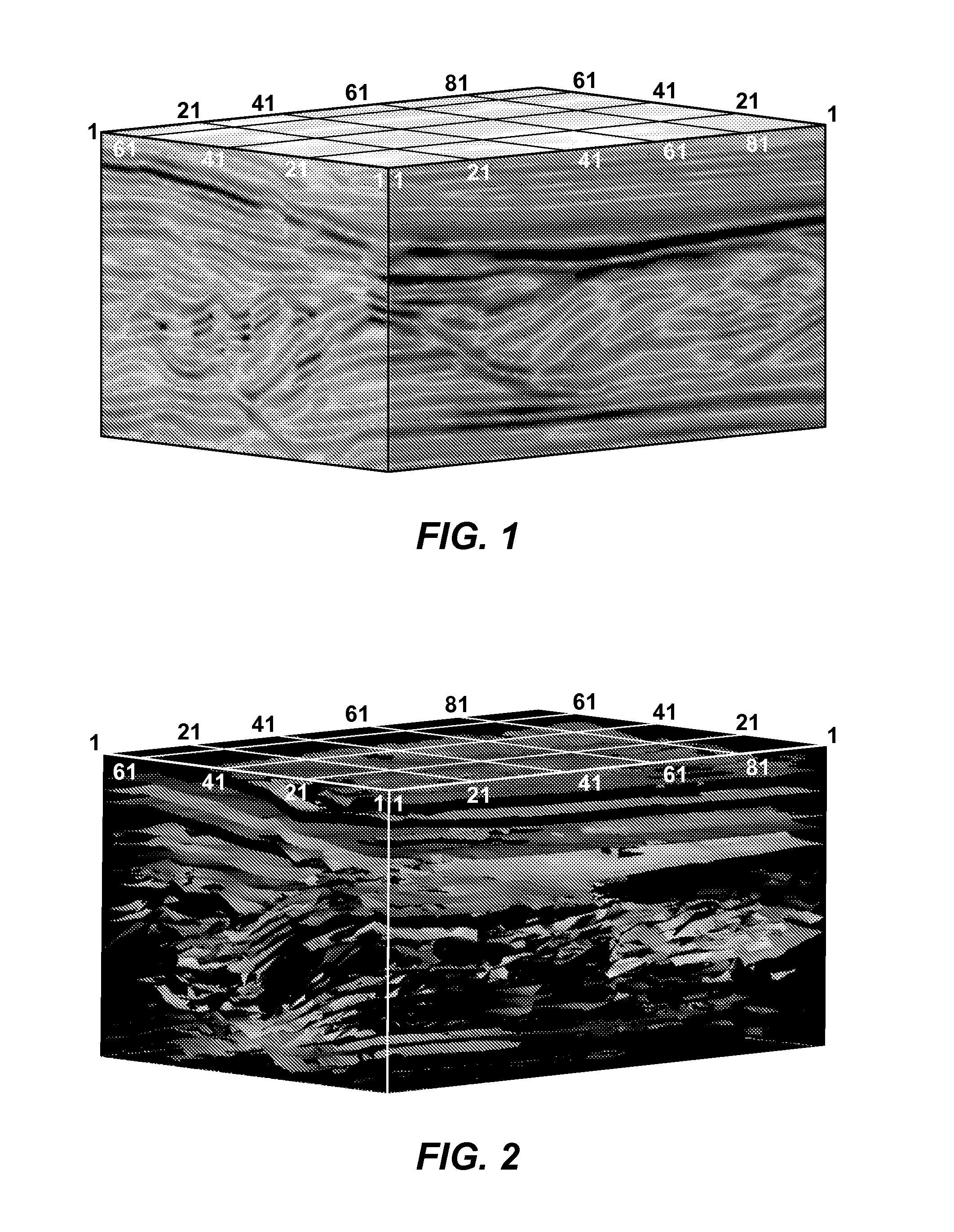
[0056]In order to search for hydrocarbon accumulations in the earth, geoscientists are using methods of remote sensing to look below the earth's surface. A routinely used technique is the seismic reflection method where man-made sound waves are generated near the surface. The sound propagates into the earth, and whenever the sound passes from one rock layer into another, a small portion of the sound is reflected back to the surface where it is recorded. Typically, hundreds to thousands of recording instruments are employed. Sound waves are sequentially excited at many different locations. From all these recordings, a two-dimensional (2D) or three-dimensional (3D) image of the subsurface can be obtained after data processing. Seismic interpretation often involves the picking of surfaces to characterize the subsurface for the delineation of underground features relevant to the exploration, identification and production of hydrocarbons. The present invention describes a method to pick ...


PUM


Abstract

Method for analysis of hydrocarbon potential of subterranean regions by generating surfaces or geobodies and analyzing them for hydrocarbon indications. Reflection-based surfaces may be automatically created in a topologically consistent manner where individual surfaces do not overlap themselves and sets of multiple surfaces are consistent with stratigraphic superposition principles. Initial surfaces are picked from the seismic data (41), then broken into smaller parts (“patches”) that are predominantly topologically consistent (42), whereupon neighboring patches are merged in a topologically consistent way (43) to form a set of surfaces that are extensive and consistent (“skeleton”). Surfaces or geobodies thus extracted may be automatically analyzed and rated (214) based on a selected measure (213) such as one or more direct hydrocarbon indications (“DHI”), e.g. AVO classification. Topological consistency for one or more surfaces may be defined as no self overlap plus local and global consistency among multiple surfaces (52).

Description

CROSS-REFERENCE TO RELATED APPLICATIONS[0001]This application claims the benefit of U.S. Provisional application 61 / 128,547 which was filed on May 22, 2008; U.S. Provisional application 61 / 131,484 which was filed on Jun. 9, 2008 and U.S. Provisional application 61 / 169,122 which was filed on Apr. 14, 2009.FIELD OF THE INVENTION[0002]This invention relates generally to the field of geophysical and geologic prospecting, and more particularly to the analysis of seismic data. Specifically, the invention is a method to create objects such as surfaces and geobodies, and to automatically analyze them with the purpose of highlighting regions with a potential to contain hydrocarbons. One particular embodiment of the invention is the simultaneous creation and analysis of many stratigraphically consistent surfaces from seismic data volumes.BACKGROUND OF THE INVENTION[0003]It is advantageous in seismic data processing and interpretation to reduce a seismic data volume to its internal reflection-...

Claims


Application Information

Patent Timeline
IPC IPC(8): E21B43/00G01V1/00
CPCG01V1/32G01V2210/63G01V2210/48G01V2210/66G01V2210/641G01V2210/643G01V1/302G01V1/345
Inventor IMHOF, MATTHIAS G.GILLARD, DOMINIQUE G.HUSSENOEDER, STEFANPAVEL, DIMITROVTERRELL, MARTINKUMARAN, KRISHNANSCHROEDER, FRED
Owner IMHOF MATTHIAS G
Why Eureka
Try Eureka