Device and method for detecting the loading of pivoted rotor blades

Inactive Publication Date: 2011-03-03
PRUTECHNIK DIETER BUSCH AG
View PDF5 Cites 13 Cited by
  • Summary
  • Abstract
  • Description
  • Claims
  • Application Information

AI Technical Summary

Benefits of technology

[0009]One special advantage of the invention is that the rotor blade loading to be detected is not determined in the rotor blade itself as in U.S. Publication No. 2009/0169357 A1, but in the vicinity of the rotor hub or in the rotor hub itself. It is not necessary to bridge distances of more than 10 m within the rotor blade or to transmit signals wirelessly or via slip rings from the rotor blade into the hub or the gondola of the wind power plant.
[0010]An electronic evaluation device establishes the relationship between the deformation of the bearing ring and the loading of the rotor blade. This electronic evaluation device can be integrated into other electronic controls, such as the control of rotor blade adjustment, which is often mounted in the rotor hub of the wind power plant, or the control of the entire wind power plant in the gondola.
[0011]In one advantageous embodiment of the invention, a one-dimensional or multidimensional inclinometer is additionally incorporated into the measurement device. The angular position of the rotor hub in the direction of rotation is detected via this inclinometer. If the inclinometer also detects a tilt of the direction which is axial with reference to the rotation of the rotor hub, the tilt of the gondola of the wind power plant is also detected.
[0012]With this measurement device, it is possible to detect both aerodynamic loads on the rotor blade and also mechanical ones which are caused, for example, by imbalances. These loads can then be used in the evaluation unit t

Problems solved by technology

Therefore, the direct measurement of the loading of rotor blades is associated with problems because strain gauges are either unreliable or, if they are made with fiber optics, are very expensive.
The direct measurement of the loading of the rotor blades should take place distributed over the length of the rotor blade; this is difficult at the current extensions of rotor blades of more than 5

Method used


Image

  • Device and method for detecting the loading of pivoted rotor blades
  • Device and method for detecting the loading of pivoted rotor blades
  • Device and method for detecting the loading of pivoted rotor blades

Examples


Embodiment Construction

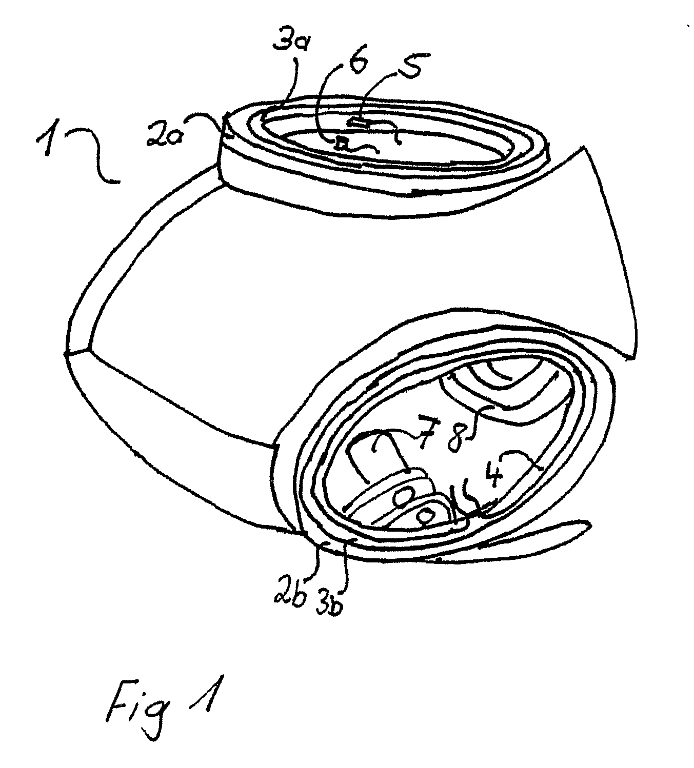
[0018]FIG. 1 shows a rotor hub 1 of a wind power plant which is intended, here, for accommodating three rotor blades. The rotor blades are pivotally mounted in outer bearing rings 2a, 2b and inner bearing rings 3a, 3b (the third bearing ring is not shown). The angular position of the rotor blades can be changed by way of a drive 7. The connection to gearing in the gondola of the wind power plant takes place via the main bearing 8.

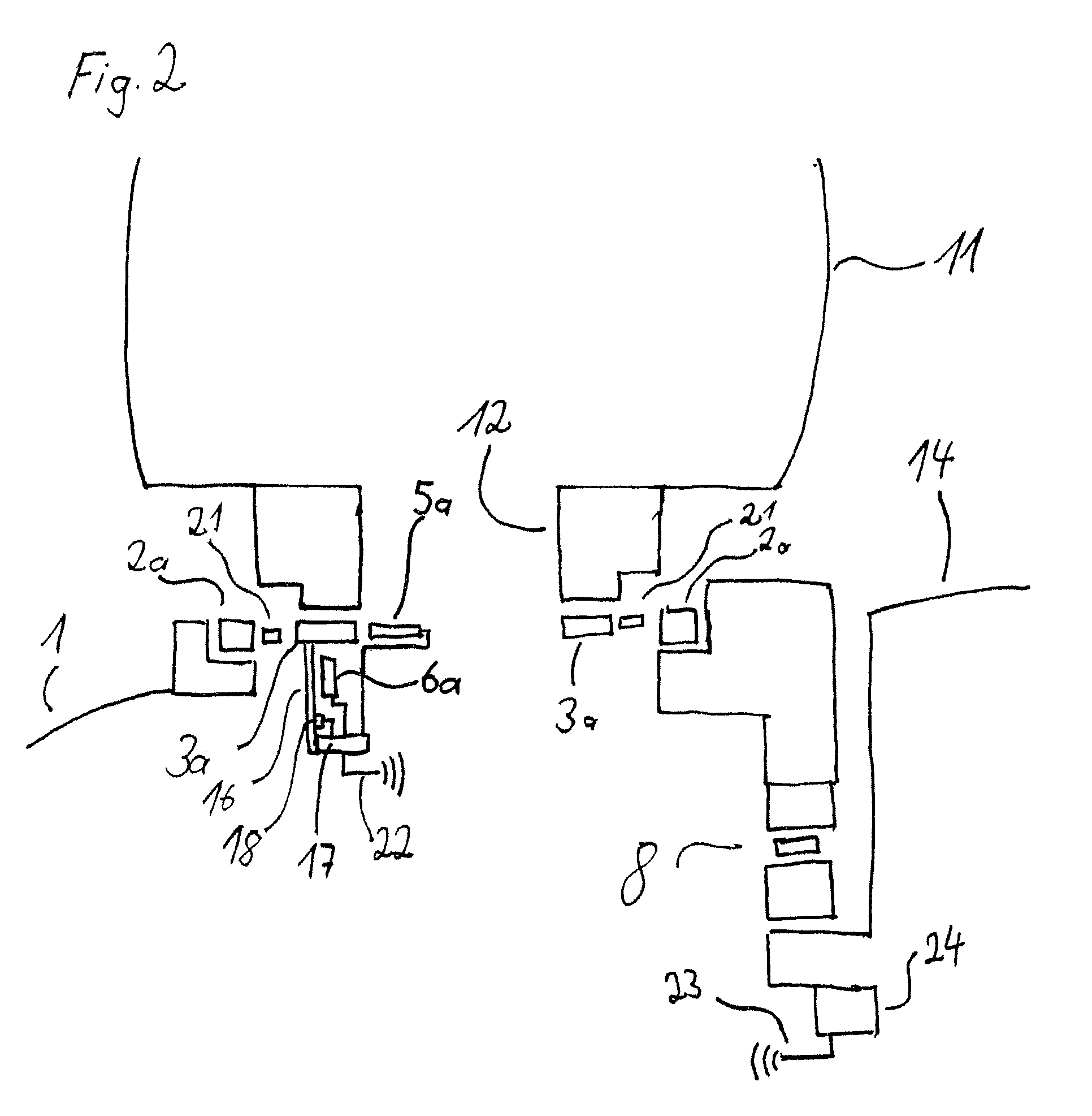
[0019]The inner ring 3a is monitored using two proximity sensors 5, 6. These proximity sensors are securely joined to the rotor hub 1 by way of holding devices (not shown). The proximity sensors detect deformation of the bearing ring 3a. These proximity sensors 5, 6 can be inductive sensors. Here, the sensor 5 measures deformation in the radial direction relative to the axis of rotation of the bearing. The sensor 6, conversely, measures deformation in the axial direction relative to the axis of rotation of the bearing. These proximity sensors are connected ...


PUM


Abstract

A method and a device for measuring the loading on rotor blades, especially of wind power plants with swiveling rotor blades, the loading of the rotor blades being determined by way of deformation of a bearing ring of the swiveling rotor blade takes place economically with proximity sensors, but can also take place advantageously with fiber optic sensors. With an electronic evaluation device, the deformation of the bearing ring is referenced to the loading of the rotor blade. In one advantageous embodiment, an inclinometer is also provided.

Description

BACKGROUND OF THE INVENTION[0001]1. Field of the Invention[0002]The invention relates to a device and method for detecting the loading of rotor blades when the latter are suspended in a rotary bearing arrangement. These pivoted rotor blades are used in wind power plants, and also in helicopters.[0003]2. Description of Related Art[0004]U.S. Patent Application Publication 2009 / 169357 A1 (European Patent Application EP 2 075 561 A2) discloses a method and a device with which rotor blades loads are measured. Here, proximity sensors or strain gauges are used. Attachment of these sensors to or in the vicinity of the main shaft or in the vicinity of the bearings is preferred for adjusting the angle of the rotor blades. This application relates to the problem of two coordinate systems for measurement with reference to the gondola of a wind power plant and with reference to the rotor hub.[0005]International Patent Application Publication WO 2009 / 095025 A1 suggests measuring the loading of th...

Claims


Application Information

Patent Timeline
IPC IPC(8): H02P9/04G01L1/04
CPCF03D1/065F03D11/00F05B2260/74Y02E10/722G01L5/0023Y02E10/721F05B2260/80F03D17/00Y02E10/72
Inventor BECKER, EDWINLOESL, JOHANN
Owner PRUTECHNIK DIETER BUSCH AG
Why Eureka
Try Eureka