
Current measuring device by means of magnetically sensitive sensor for a power electronics system

a technology of magnetically sensitive sensors and power electronics, which is applied in the direction of printed circuit board receptacles, electrical apparatus construction details, instruments, etc., can solve the problems of increasing the need for installation space, and achieve the effect of improving the vibration resistance, high vibration resistance of the current measuring device, and high installation space compaction

Active Publication Date: 2011-03-03
VITESCO TECH GERMANY GMBH
View PDF10 Cites 13 Cited by
  • Summary
  • Abstract
  • Description
  • Claims
  • Application Information

AI Technical Summary

Benefits of technology

[0013]This method enables a further compaction of the existing installation space. For overmoulding with glass fibre-reinforced plastic, no further process step is necessary. It already occurs to fix the busbars and the fixing elements. Full overmoulding of the soft magnetic core and the magnetically sensitive sensor with glass fibre-reinforced plastic leads to a high vibration resistance of the current measuring device.
[0014]For producing a power electronics system in which a second circuit board comprises control electronics of the circuit breaker and evaluation electronics of the current measuring device, the soft magnetic core may be fixed in the fr

Problems solved by technology

The plug connections provided for this device are not needed in all power electronics systems with c

Method used


Image

  • Current measuring device by means of magnetically sensitive sensor for a power electronics system
  • Current measuring device by means of magnetically sensitive sensor for a power electronics system
  • Current measuring device by means of magnetically sensitive sensor for a power electronics system

Examples


Embodiment Construction

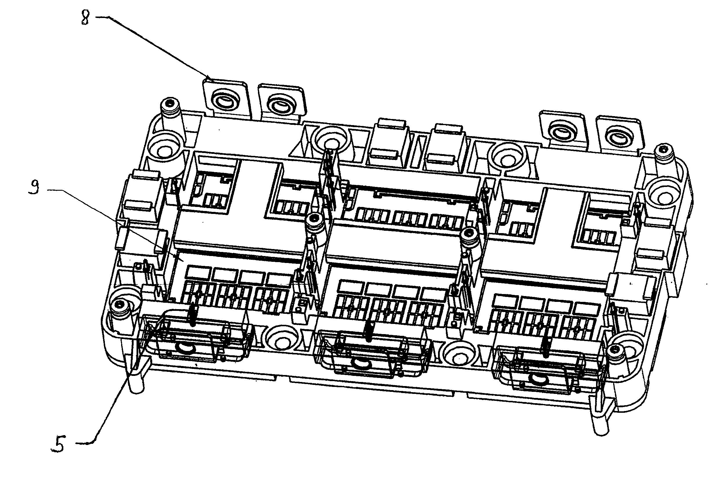
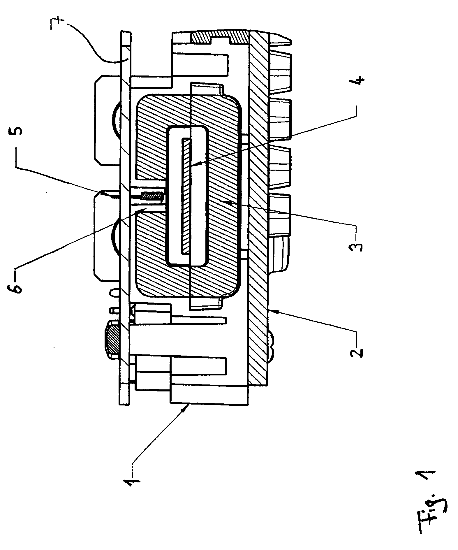
[0018]In the cross section according to FIG. 1, an electrical conductor (4) which runs vertically to the sectional plane is represented. The current which flows through the conductor (4) is measured by the measuring device. For this purpose, the measuring device comprises a soft magnetic core (3) which is arranged in the frame (1). “In the frame (1)” means here that the soft magnetic core (3) is fully overmoulded with plastic in the area of the frame (1) according to a method described below.

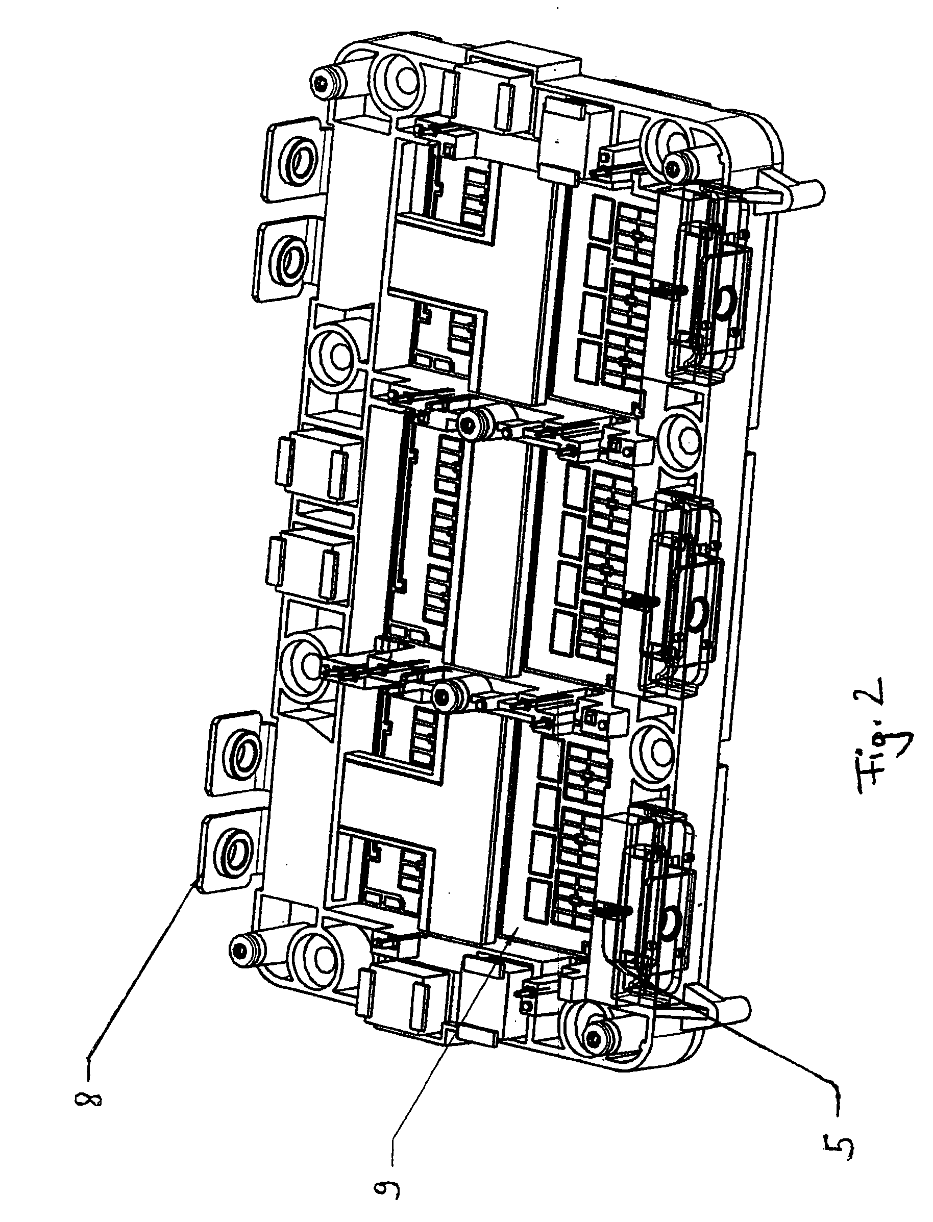
[0019]The frame (1) surrounds the circuit board on which the power electronics components are arranged in a circuitry. The electrical conductor (4) is guided through the frame (1).

[0020]FIG. 1 shows the soft magnetic core (3) surrounding the insulation of the electrical conductor (4), which core is open at one location (6), in accordance with a preferred embodiment of the current measuring device. A magnetically sensitive sensor (5), preferably a Hall sensor, is arranged in the recess (6) of the...


PUM

PropertyMeasurementUnit
Strengthaaaaaaaaaa
Sensitivityaaaaaaaaaa
Soft magnetismaaaaaaaaaa

Abstract

A current measuring device in a power electronics system includes at least one circuit board and an electrical conductor which is guided through a frame surrounding the circuit board. The current measuring device includes a soft magnetic core surrounding the insulation of the electrical conductor, which core is arranged in the frame. The soft magnetic core is open at one location. A magnetically sensitive sensor, in particular a Hall sensor, is arranged in the recess of the soft magnetic core surrounding the insulation of the electrical conductor in order to detect the magnetic field strength.

Description

CROSS REFERENCE TO RELATED APPLICATIONS[0001]This application is the U.S. national phase application of PCT International Application No. PCT / DE2009 / 000272, filed Feb. 27, 2009, which claims priority to German Patent Application No. 10 2008 012 665.9, filed Mar. 5, 2008, which are both incorporated by reference in their entirety.FIELD OF THE INVENTION[0002]The invention relates to a current measuring device in power electronics systems. Power electronics systems in which current measuring may be required are for example pulse-controlled inverters, on-board voltage converters and battery monitoring equipment.BACKGROUND OF THE INVENTION[0003]DE 102006006314 A1, which is incorporated by reference, shows a device for current measuring which is integrated in a plug connection. For current sensing, at least one Hall sensor is arranged in a slit of an electrical conductor of the plug connection. The plug connection comprises a power pin which is arranged on a circuit board via a phase insu...

Claims


Application Information

Patent Timeline
IPC IPC(8): G01R33/06G01R19/00H05K13/00
CPCH05K1/141G01R15/207H05K7/1432Y10T29/49002H05K7/14329
Inventor KRELLA, UWEMATTHES, KATRINHIEMER, GERHARD
Owner VITESCO TECH GERMANY GMBH
Learn More