Rotary transformer

Active Publication Date: 2011-03-03
AKER SOLUTIONS AS
View PDF0 Cites 40 Cited by
  • Summary
  • Abstract
  • Description
  • Claims
  • Application Information

AI Technical Summary

Benefits of technology

[0017]It is therefore an object of the present invention to review suitability of electrical power from shore for a weather vaning FPSO concept or alternatively electrical power exchange with other installations such as wind mills, including offshore wind turbines. It is another object to disclose a solution that contributes to reduction of green house emissions from offshore oil and

Problems solved by technology

One of the largest known slip ring based swivel in operation have an maximum power in the 40 MVA range, but they all have disadvantages of being subject to friction, wear, intermittent contact, and they have limitations on the currents and voltage levels that can be accommodated with the available space versus risk for electrical or mechanical damage.
These are some of the limitations that make it difficult to provide electrification of the FPSO's.
No local cogeneration, i.e. total electrification, with 36 kV power from a remote source could give cases with voltage instability.
A similar problem is present in relation to wind turbines where the turbine as adapted to head toward the wind and thus be able to rotate relative to the vertical axis.
As the world becomes more and more populated the lack of space is a problem regarding wind turbine locations.
The existing types of wind turbines, such as for exa

Method used


Image

  • Rotary transformer
  • Rotary transformer
  • Rotary transformer

Examples


Example

DETAILED DESCRIPTION OF THE DRAWINGS

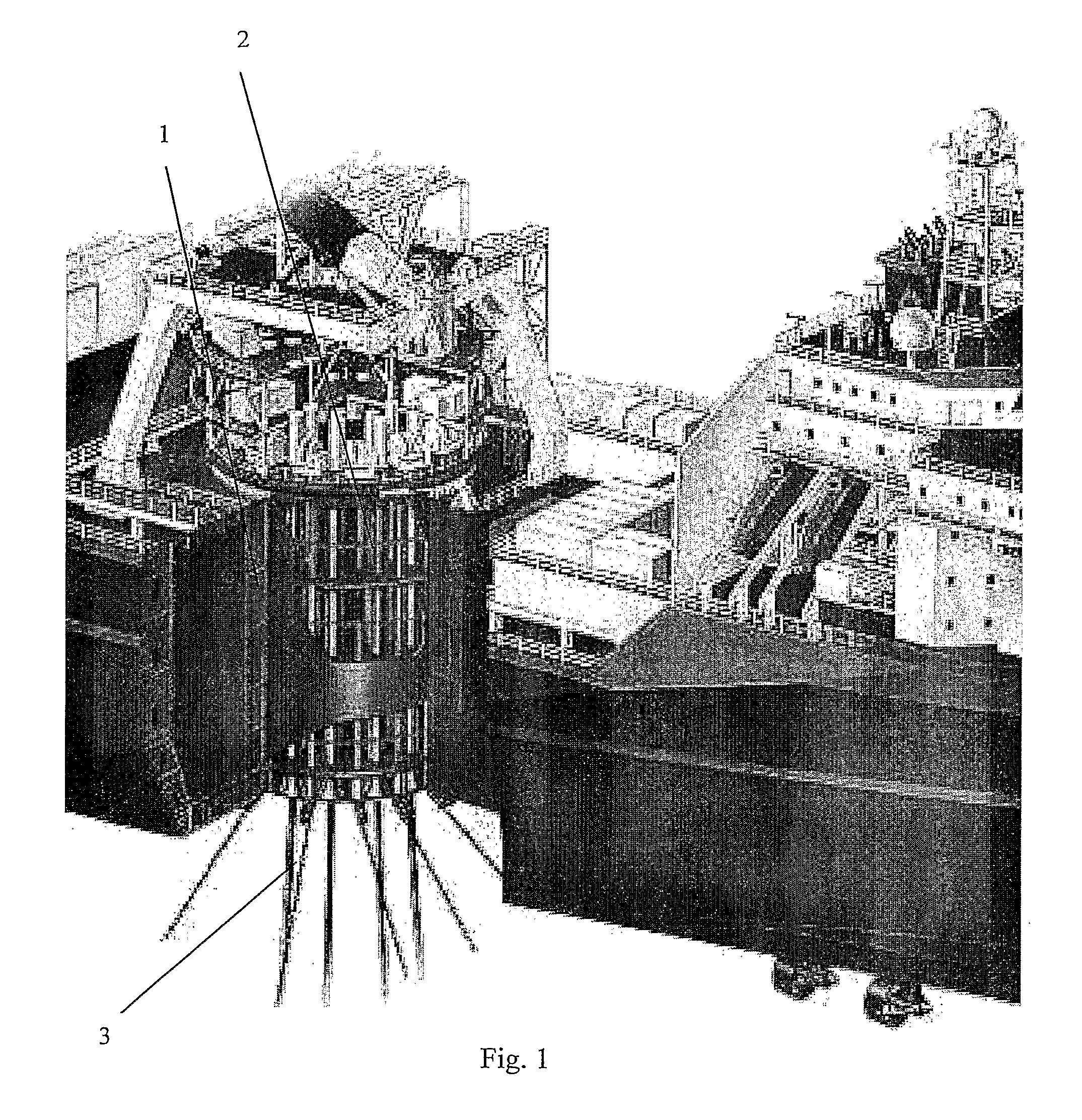
[0053]As seen in FIG. 1, the weather vaning FPSO comprises a turret 2 surrounded by a hull 1. The turret 2 has typically a hole in the middle where risers, anchor lines etc. are positioned. The weather vaning FPSO will naturally move due to wind, ocean currents, waves etc., but the risers, anchor lines needs to be relatively stationary to avoid being tangled. Thus, the turret 2 is stationary and the hull 1 of the FPSO is rotating around the turret 2. There are different types of turrets 2, and an example turret is a Tentech turret as shown in FIG. 1.

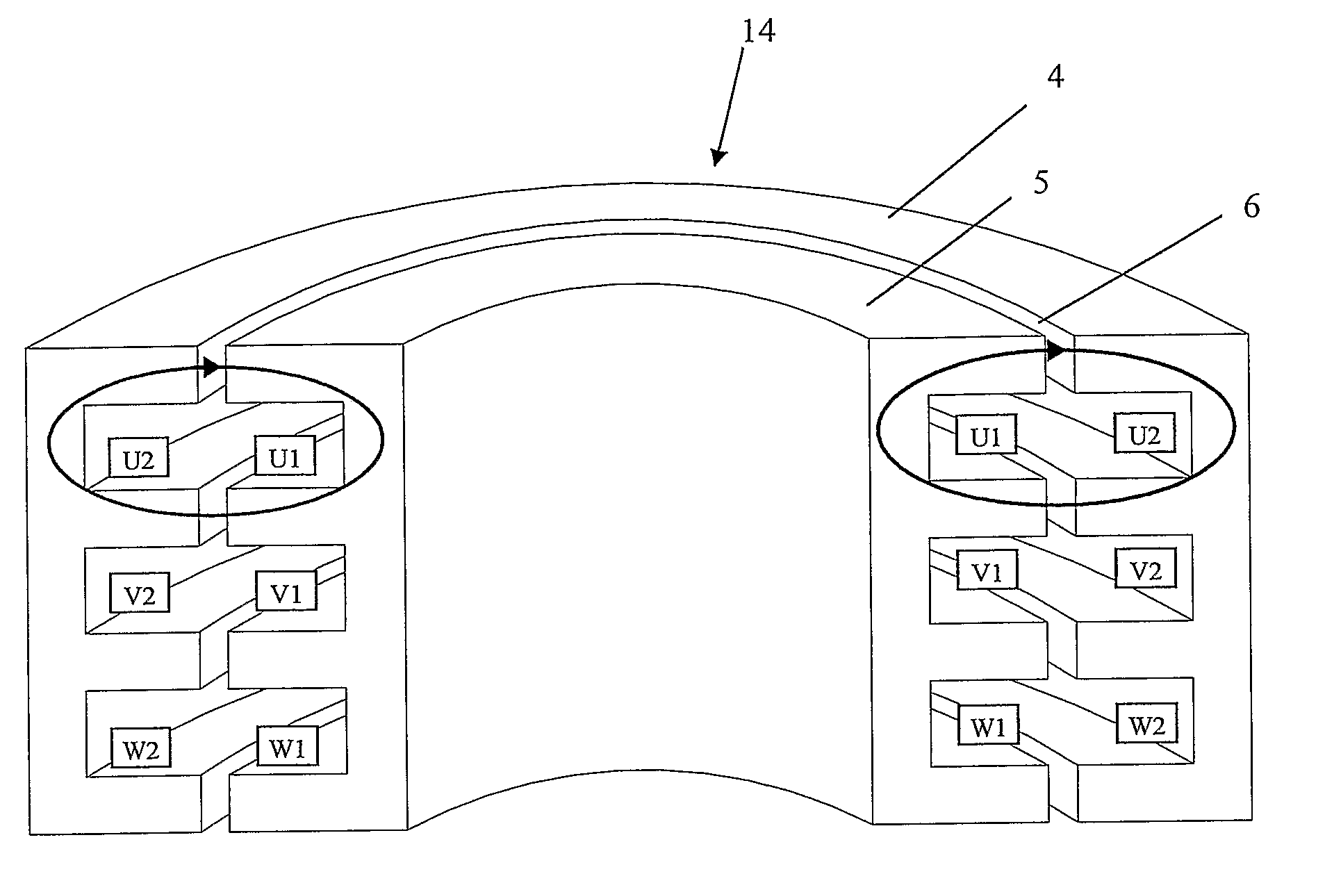
[0054]As mentioned above, power and voltage level limits of the current technology that uses an electrical power swivel on the turret 2 can be avoided by installing a three-phase rotary transformer with the turret 2 on the FPSO instead—preferably a transformer with cast resin windings or other dry cable technology that does not require oil to cool and insulate a transformer with capabilities up to and ...


PUM


Abstract

A system for high power transmission on an installation comprising a first part (1, 11) and a second part (2, 12) rotating relative to each other characterized in that the system further comprising a rotary three-phase transformer having primary (U1, V1, W1) and secondary (U2, V2, W2) windings, the first part being provided with one of said primary (U1, V1, W1) or secondary (U2, V2, W2) windings, the second part being provided with the remaining winding of said primary (U1, V1, W1) or secondary (U2, V2, W2) windings, said primary (U1, V1, W1) and secondary (U2, V2, W2) windings are arranged to face each other, and an air gap (6) is provided between the primary (U1, V1, W1) and secondary (U2, V2, W2) windings and their corresponding parts of the transformer cores.

Description

FIELD OF THE INVENTION[0001]This invention relates to electrical power transmission on, to and / or from offshore vessels, and more particularly the present invention relates to electrical power transmission, e.g. on a weather vaning FPSO or wind turbine using a three phase rotary transformer.BACKGROUND OF THE INVENTION AND PRIOR ART[0002]The issue of climate and global warming is a hot topic nowadays. A Norwegian governmental report discussed aspects of the electrification of new and existing devices on the Norwegian continental shelf with power from the mainland that would reduce the green house gas emission form the petroleum sector. One type of offshore oil and gas installations that need to be electrificated are so called Floating Production Storage and Offloading (FPSO). The FPSO's can be divided in two main groups by their strategy for seaworthiness:[0003]Ship shaped FPSO with a turret in order to enable mooring independent weather vaning.[0004]Non weather vaning FPSO concepts ...

Claims


Application Information

Patent Timeline
IPC IPC(8): H01F38/18
CPCB63B21/50H01F3/02Y02B10/30H01F38/18H01F30/12H01R13/005Y02E10/72
Inventor BJERKNES, OLE JOHANKLEMETSEN, SVEIN OLAFLIVERUD, JON
Owner AKER SOLUTIONS AS
Why Eureka
Try Eureka