
Security tag assembly

Active Publication Date: 2011-03-03
BRAEBURN ASSET HLDG +1
View PDF69 Cites 16 Cited by
  • Summary
  • Abstract
  • Description
  • Claims
  • Application Information

AI Technical Summary

Benefits of technology

[0015]More specifically, various operative and structural details of the aforementioned detachment assembly is such as to facilitate the initial application of the plurality of detachment members through the base and into the aforementioned gripping engagement with the release member. Subsequent to establishment of the gripping engagement with the release member, the detachment assembly is operative to pull or otherwise force the plurality of detachment members outwardly from the base. As a result, an outwardly directed, pulling force will be exerted on the release member concurrent to the attempted outwardly directed movement of the plurality of the detachment members. The established gripping engagement between the plurality of detachment members and the release member will be sufficient to force movement of the release member into driving, displacing engagement with the locking assembly. In turn, the locking assembly will be forced outwardly or away from the attachment pin and from its locking orientation relative thereto, thereby allowing the tag assembly affixed to the attachment pin to be removed from the base in an authorized manner. As set forth above the product or merchandise to which the security tag assembly is connected can thereby be removed from the monitored area, such as when being purchased.
[0017]In order to facilitate the above described interaction between the plurality of detachment members and the release member, to define the gripping engagement therebetween, the alignment assembly is disposed, structured and configured to properly align the base and more specifically the at least some plurality of access openings with the detachment members associated with the detachment assembly. As such, the disposition and configuration of the alignment assembly is such as to accomplish the predetermined and preferred alignment. Such a predetermined structural configuration of the alignment assembly may include, but is not limited to, a multi-sided peripheral configuration such as being in the form of a multi-sided figure including, but not limited to, a square, rectangular, triangle pentagon, star-shape, or other multi-sided peripheral configuration. At least a portion of the detachment assembly is cooperatively structured with the alignment assembly to receive it and facilitate and easy and quick orientation of the base such that alignment between the detachment members and the access openings / receiving channels is accomplished.
[0019]Therefore, the various preferred embodiments of the security tag assembly of the present invention overcomes many of the problems and disadvantages associated with conventional or previously known security systems. Further, the various preferred embodiments of the security tag assembly comprises simple, efficient practical structure which facilitates, the attachment, removal and efficient practicing of security procedures so as to prevent or at least significantly restrict the unauthorized removal of protected merchandise or products from a given area.

Problems solved by technology

More specifically, it is believed that such security tag devices serve as a deterrent to unauthorized removal in that a potential thief will recognize that the merchandise will be “stained” or otherwise marked, thereby rendering the merchandise useless, upon forced removal of the security tag.
While popular, it is recognized that a significant number of the anti-theft tags currently being utilized include problems or disadvantages which render them less than totally efficient.
More specifically, wide spread knowledge of the structural features of such security tags allows unauthorized personnel to develop techniques which are specifically designed to remove the tag from the merchandise in a manner which defeats the aforementioned indicator structures.

Method used


Image

  • Security tag assembly
  • Security tag assembly
  • Security tag assembly

Examples


Embodiment Construction

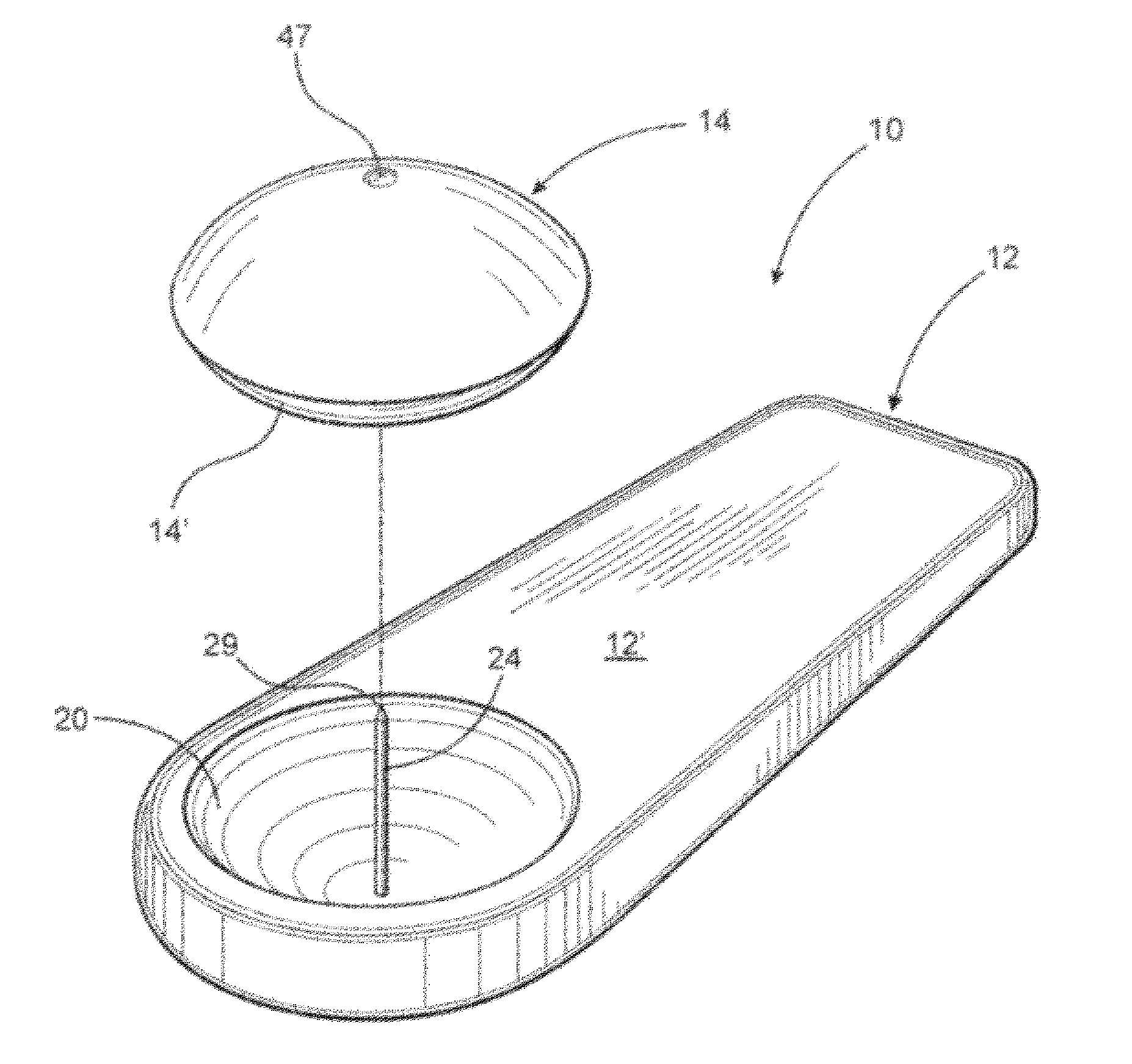
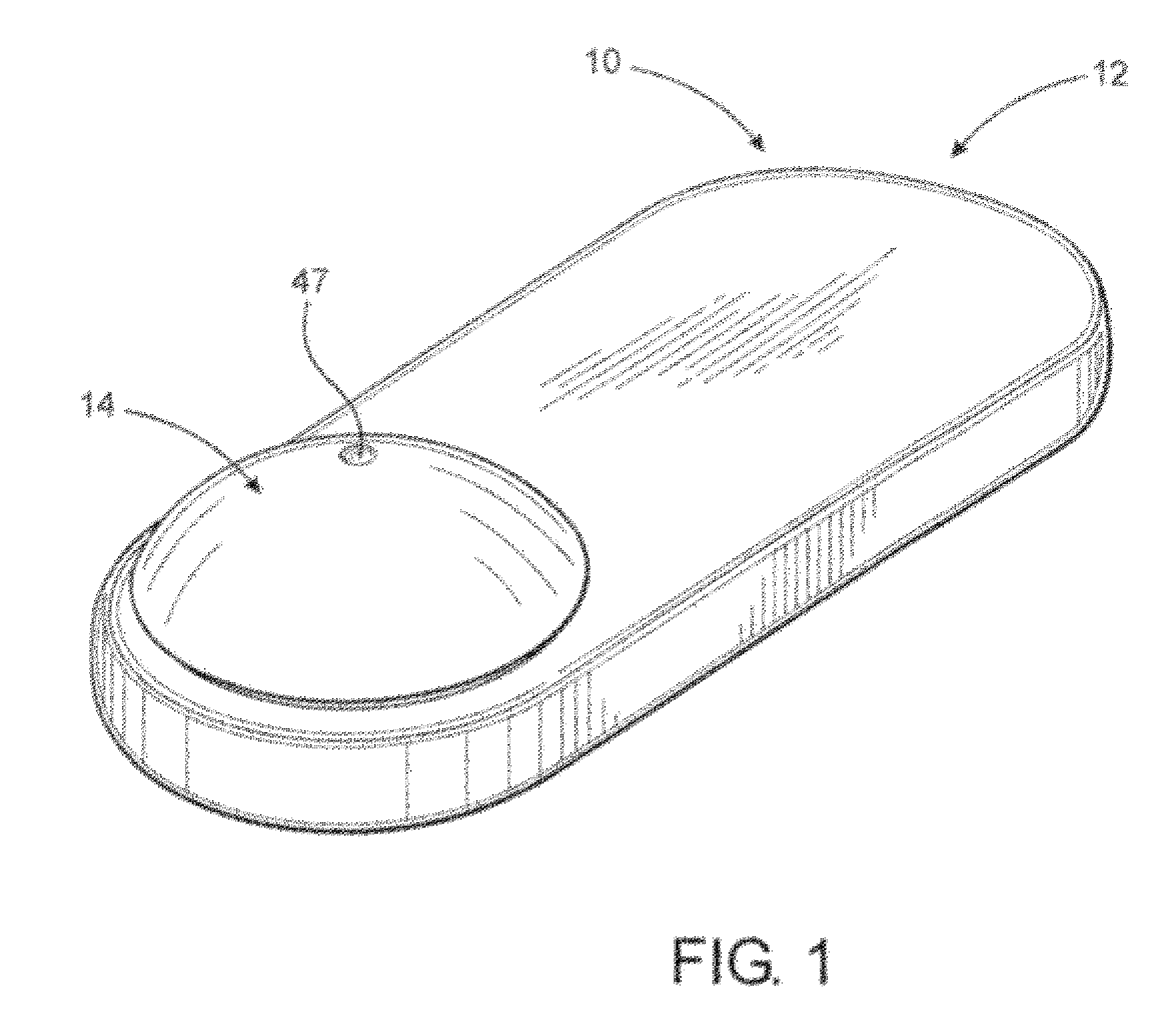
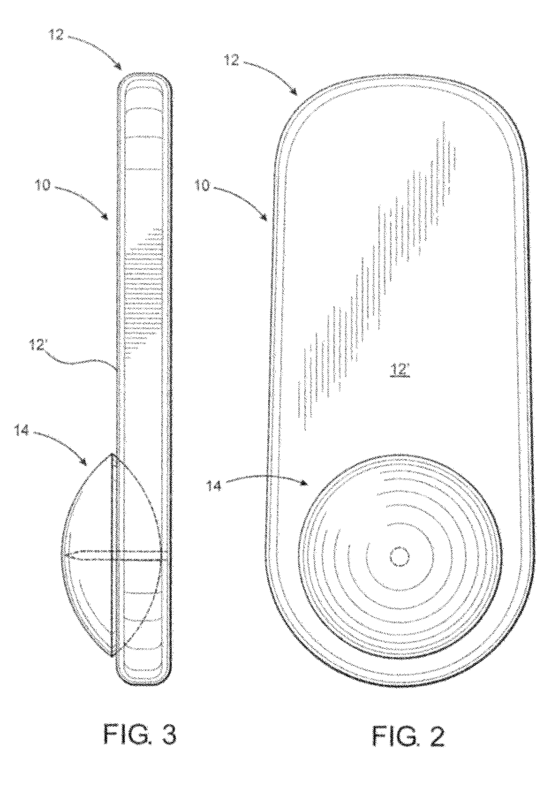
[0052]As shown in the accompanying drawings, the present invention is directed towards a security tag assembly generally indicated as 10 and comprising at least one base 12 and at least one attachment member 14. However, a practical application of the present invention would typically involve a plurality of bases 12 and a plurality of attachment members 14, such as when a plurality of different products were being protected and / or monitored. Moreover, the security tag assembly 10 is of the type structured to be removably secured to various types of merchandise 18 so as to prevent unauthorized removal of the merchandise 18 from a given area or location. Typical applications for the security tag assembly 10 of the present invention include the interconnecting of one base 12 and any one of a plurality of attachment members 14 to merchandise 18 being protected. As such, removal of the security tag assembly 10 from its operative position can be quickly and easily accomplished by authoriz...


PUM


Abstract

A security tag assembly and security system associated therewith to prevent the unauthorized removal of merchandise from a given area, such as a retail establishment. The security tag assembly comprises a base and at least one tag member removably connected in an operative position on the merchandise being protected. A locking assembly is structured to restrict detachment of the tag member and is forcibly disposed out of a locking orientation relative to said tag member. A detachment assembly and a data registering processor may include a two-way communication link which facilitates processing of the merchandise data disposed on the security tag assembly, such that the purchasing of the merchandise and the removal of the security tag assembly can be effectively accomplished without jeopardizing the security of the merchandise being sold.

Description

CLAIM OF PRIORITY [0001]The present application is a continuation-in-part application having Ser. No. 12 / 316,586, filed on Dec. 12, 2008, now U.S. Pat. No. 7,817,041, which matured on Oct. 19, 2010, which is a continuation-in-part application of a previously filed, now pending application having Ser. No. 12 / 217,613, filed on Jul. 7, 2008, which is a continuation-in-part application of U.S. patent application having Ser. No. 11 / 805,307, filed on May 23, 2007, now U.S. Pat. No. 7,474,216, which matured on Jan. 6, 2009, which is a continuation-in-part of U.S. patent application having Ser. No. 11 / 363,436, filed on Feb. 27, 2006, now U.S. Pat. No. 7,286,054, which matured on Oct. 23, 2007, which is a continuation-in-part of U.S. patent application having Ser. No. 11 / 056,565, filed on Feb. 11, 2005, now U.S. Pat. No. 7,382,256, which matured on Jun. 3, 2008, which is a continuation-in-part application of a previously filed, now abandoned application having Ser. No. 11 / 008,641, filed on D...

Claims


Application Information

Patent Timeline
IPC IPC(8): G08B13/14
CPCE05B73/0017G08B13/2402E05B73/0064
Inventor SKJELLERUP, JOHANSTENILD, EDDIE L.
Owner BRAEBURN ASSET HLDG
Learn More