LED lighting apparatus

a technology of led lighting and led light, which is applied in the direction of lighting and heating apparatus, fixed installation, semiconductor devices for light sources, etc., can solve the problems of high replacement cost, limitation of utilizing led lighting apparatus and diffusing light, and inability to replace conventional lighting apparatus using filament, etc., to achieve the effect of maximizing the utilization degree of led lighting apparatus, simple and efficient radiation structure, and maximizing the utilization degr

Inactive Publication Date: 2016-12-15
KIM YOUNG WAN
View PDF5 Cites 2 Cited by
  • Summary
  • Abstract
  • Description
  • Claims
  • Application Information

AI Technical Summary

Benefits of technology

[0044]The LED lighting apparatus of the present invention may have the advantage in that since an LED device is installed on one or more metallic plates, heat generated from the LED device is transmitted to the metallic plate to thus be radiated. Such a radiation structure is simple and efficient.
[0045]In addition, the LED lighting apparatus of the present invention may have the advantage in that since the LED lighting apparatus of the present invention has a similar light irradiation effect to a light bulb, as it is implemented as a pair of metallic plates to which LED devices are coupled to surfaces opposite to facing surfaces, the LED lighting apparatus of the present invention can maximize its utilization degree by replacing the light bulb used in the conventional lighting apparatus.
[0046]In particular, the conventional illumination equipment using a light bulb is provided with a reflector, and the reflector is optimized in correspondence to a light emitting part of a light bulb. In the LED lighting apparatus of the present invention, an LED device is installed on one or more metallic plates, in this case, the LED device is positioned in correspondence to a light emitting part of the conventional light bulb, thereby having a similar light irradiation effect to the light bulb. As the LED lighting apparatus of the present invention replaces the light bulb used in the conventional lighting apparatus, a utilization degree of the LED lighting apparatus can be maximized.
[0047]When the LED lighting apparatus of the present invention is applied to a headlight, a fog lamp, a turn signal lamp, etc. for automobile, there are the following advantages.
[0048]Firstly, when the LED lighting apparatus of the present invention is applied to a headlight, a fog lamp, a turn signal lamp, etc. for automobile which requires a special illumination effect, the conventional lighting apparatus having a light bulb should change a design of a reflector, since the LED lighting apparatus of the present invention has a different illumination characteristic from the light bulb.
[0049]The LED lighting apparatus of the present invention is positioned in correspondence to a light emitting part of the conventional light bulb, thereby having a similar light irradiation effect to the light bulb. As the LED lighting apparatus of the present invention replaces the light bulb used in the conventional lighting apparatus, a utilization degree of the LED lighting apparatus can be maximized.

Problems solved by technology

However, the LED lighting apparatus cannot replace the conventional lighting apparatus using filament, since it has low diffusion characteristic of light due to high straight characteristic of light, and since side illuminance is weak.
In case of replacing the conventional lighting apparatus 1 by an LED lighting apparatus, replacement costs are high since a reflection member should be re-designed, etc.
This may cause limitation in utilizing the LED lighting apparatus and diffusing light.

Method used


Image

  • LED lighting apparatus
  • LED lighting apparatus
  • LED lighting apparatus

Examples


first embodiment

[0121]The power connection line 250 may be connected to each LED device 110 to be explained later, thereby being used to maintain an interval between the metallic plates 110 arranged in parallel to each other. The interval between the metallic plates 110 arranged in parallel to each other may be maintained by an interval maintenance member 280 to be explained later.

[0122]As another example, as shown in FIG. 6, the contact prevention means 111 may be implemented as an insulation member 111 of the metallic plate 110.

[0123]The insulation member 111, configured to electrically insulate the LED device 120 and the metallic plate 110 from each other, may be implemented as an insulating material coated on the surface of the metallic plate 110, an insulation tape attached onto the metallic plate 110, etc.

[0124]Unlike in FIG. 5, if only the heat slug 124 electrically insulated from the first electrode 121 and the second electrode 122 is coupled to the metallic plate 110 so as to be thermally...

second embodiment

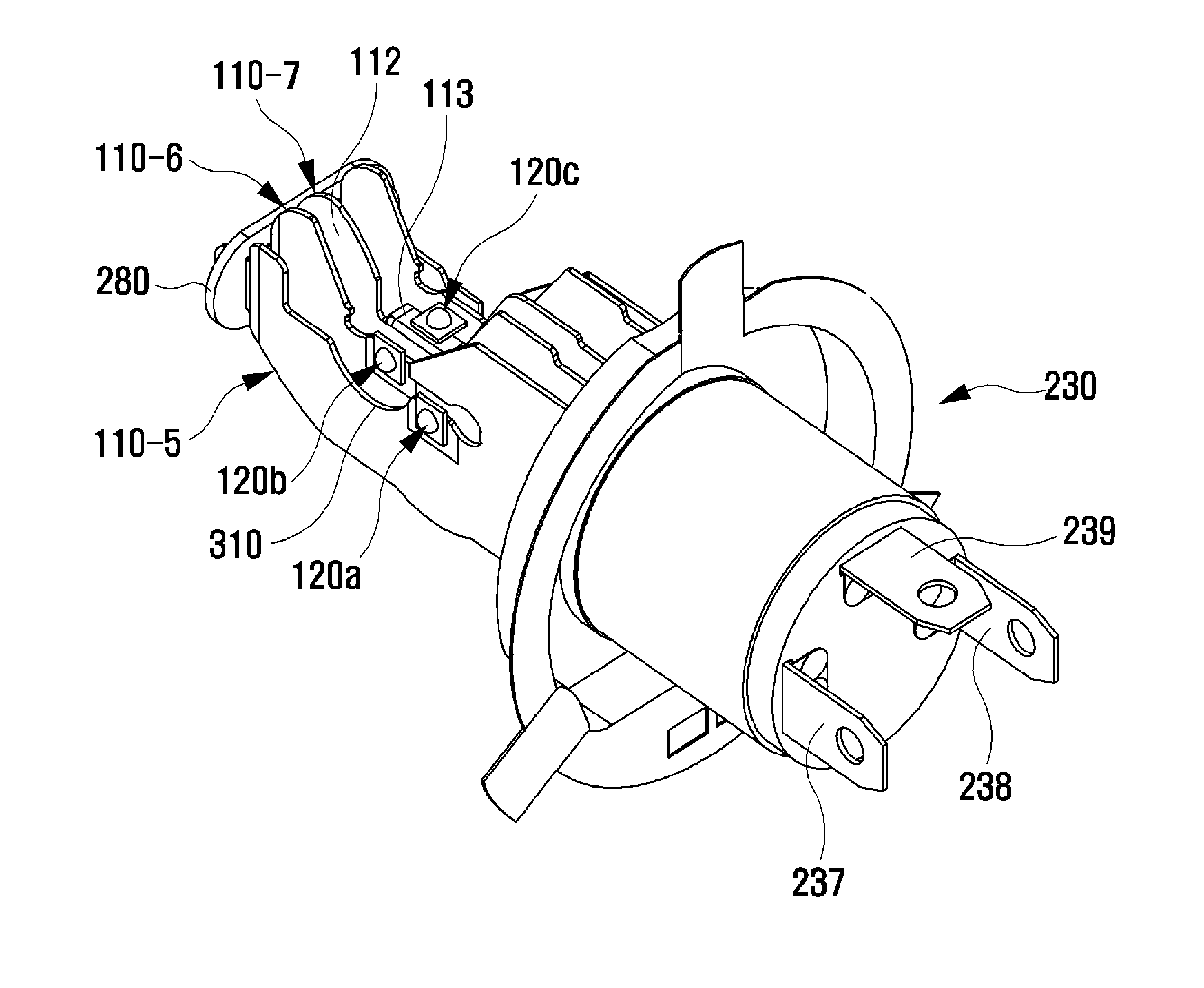
[0152]In the present invention, when a coupling direction of the socket unit 230 is a lengthwise direction, the bent metallic plate 110-1 may include one or more first bent metallic plates that a normal line of the installation portion 112 is perpendicular to the lengthwise direction, i.e., a light emitting surface of the LED device 120 is toward a lateral side, as shown in FIGS. 7 and 8.

third embodiment

[0153]In the present invention, when a coupling direction of the socket unit 230 is a lengthwise direction, the bent metallic plate 110-1 may include one or more second bent metallic plates that a normal line of the installation portion 112 is parallel to the lengthwise direction, i.e., a light emitting surface of the LED device 120 is toward a front side.

[0154]In a case where each of the metallic plate 110 and the LED device 120 is formed in plurality, an equivalent circuit thereof may be formed in parallel, in series, in series-parallel, etc., based on each LED device 120.

[0155]The metallic plate 110 may be conducted with part of the equivalent circuit, i.e., one electrode of the first and the second electrodes of the LED device 120.

[0156]In the LED lighting apparatus according to the present invention, various illumination effects may be implemented as the metallic plate where the LED device is installed is formed in plurality, and as a relative position of the LED device with re...


PUM


Abstract

Disclosed is an LED lighting apparatus, and more particularly, to an LED lighting apparatus using an LED device. The LED lighting apparatus includes: one or more metallic plates; and one or more LED devices installed on a surface of the metallic plates, wherein only one electrode of a first electrode and a second electrode of the LED device is coupled to the metallic plates.

Description

TECHNICAL FIELD[0001]The present invention relates to a light emitting diode (LED) lighting apparatus, and more particularly, to an LED lighting apparatus for illumination using LED device.BACKGROUND ART[0002]Generally, a lighting apparatus is widely used as a lighting apparatus for illuminating the inside or the outside, or a notification means such as a traffic signal light and a warning light.[0003]As the lighting apparatus, a filament which emits light by being heated to a high temperature when supplied with current is used. Recently, an LED lighting apparatus having low power consumption, high illuminance, and a long lifespan is being spotlighted.[0004]However, the LED lighting apparatus cannot replace the conventional lighting apparatus using filament, since it has low diffusion characteristic of light due to high straight characteristic of light, and since side illuminance is weak.[0005]FIGS. 1 and 2 illustrate the conventional lighting apparatus 1 having a light bulb 10 in a...

Claims


Application Information

Patent Timeline
Patent Type & Authority Applications(United States)
IPC IPC(8): F21K9/20F21S8/10
CPCF21K9/20F21S48/328F21S48/31F21S48/115F21Y2115/10F21S48/1109F21S48/212F21S48/1394F21S48/238F21S48/215F21K9/232F21K9/27F21S41/148F21S41/192F21S43/14F21S43/195F21S45/10F21S45/43F21S45/47F21Y2107/30F21Y2107/40F21K9/23F21K9/235F21K9/237F21S41/141F21S41/663F21V19/001F21V19/006F21V29/70F21V29/89F21W2102/00F21Y2101/00
Inventor KIM, YOUNG WAN
Owner KIM YOUNG WAN
Why Eureka
Try Eureka