Antenna Formed Inside Film

a technology of antenna and film, applied in the direction of antennas, antenna details, basic electric elements, etc., can solve the problems of multiband antenna realization, multiband antenna appearance, design and integration capability become a big challenge, and the radiation conductors and thin films are likely to bump

Inactive Publication Date: 2011-03-03
ADVANCED CONNECTEK INC
View PDF3 Cites 5 Cited by
  • Summary
  • Abstract
  • Description
  • Claims
  • Application Information

AI Technical Summary

Benefits of technology

[0007]One objective of the present invention is provide an antenna formed inside a film, which uses a soft conductive paste as the electric connection medium between the radiation conductor and the contact te...

Problems solved by technology

Such a requirement makes the realization of a multiband system more complicated.
Therefore, the appearance, design and integration capability of a multiband antenna become a big challenge.
Firstly, radiation conductors and circuits are stuck to the surface of a plastic casing.
However, when the contact terminals conducting el...

Method used


Image

  • Antenna Formed Inside Film
  • Antenna Formed Inside Film
  • Antenna Formed Inside Film

Examples


Embodiment Construction

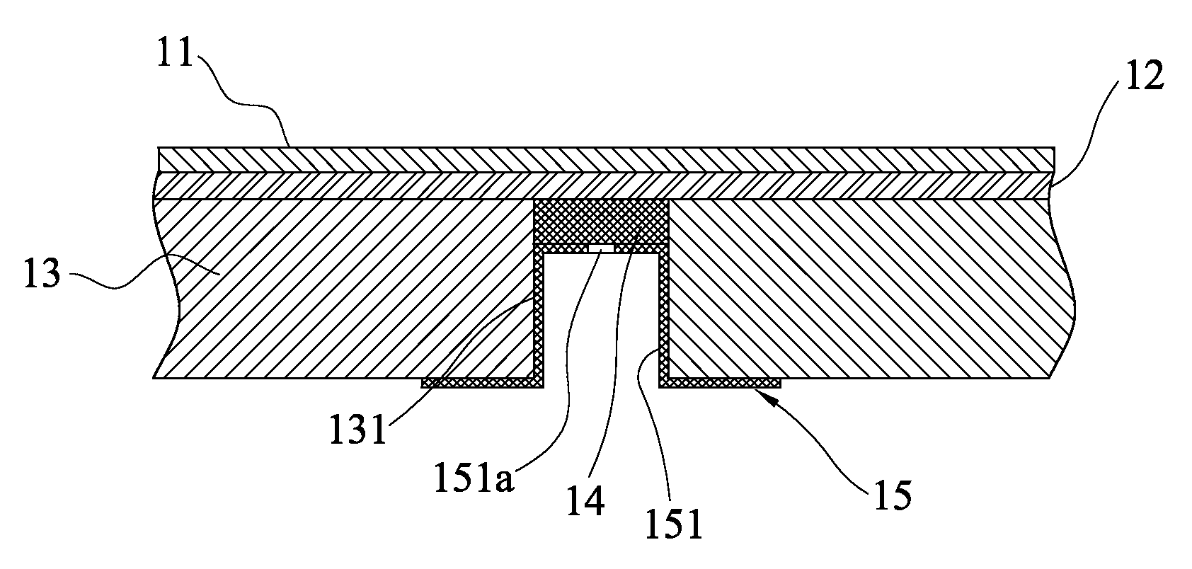
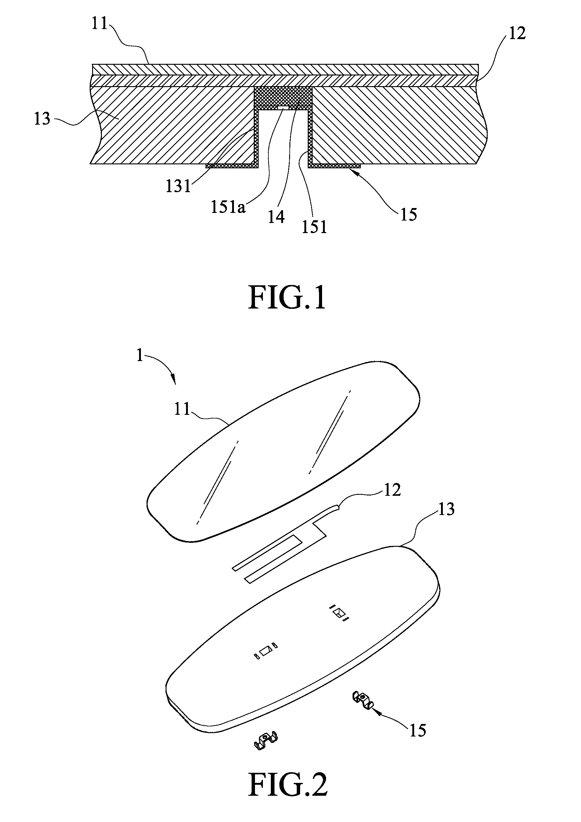
[0016]Refer to FIG. 1 a sectional view schematically showing an antenna formed inside a film according to a first embodiment of the present invention. The antenna formed inside a film of the present invention comprises a thin film 11, a radiation conductor 12, a supporter 13, a conductive paste 14 and at least one contact terminal 15. The metallic contact terminal 15 has a recession 151.

[0017]The radiation conductor 12 and the circuit are printed on the thin film 11. The thin film 11 may be a polyester film. The supporter 13 is tightly bonded to the radiation conductor 12 by pressing, and the supporter 13 has at least one trench 131. The contact terminal 15 is made of a metal sheet, and the recession 151 thereof has a preformed hole 151a. The recession 151 of the contact terminal 15 is inserted into the trench 131 with a spacing existing between the recession 151 and the patterns of the radiation conductor 12 and the circuits. Via the hole 151a, the conductive paste 14 is injected i...


PUM


Abstract

An antenna formed inside a film comprises a thin film, a radiation conductor, a supporter, a conductive paste and at least one contact terminal. The radiation conductor is arranged on the thin film. The supporter is arranged on the radiation conductor with at least one trench formed thereon. The contact terminal has a recession with a hole. The recession is inserted into the trench. The conductive paste is injected into the trench via the hole to have such a thickness that the top of the conductive paste exactly contacts the bottom of the recession. The present invention is characterized in that a conductive paste is used as a conduction medium and a buffer between the contact terminal and the radiation conductor. Thereby, the present invention can overcome the conventional problem that the radiation conductor and thin film are likely to be damaged in the fabrication process.

Description

BACKGROUND OF THE INVENTION[0001]1. Field of the Invention[0002]The present invention relates to an antenna formed inside a film, particularly to an antenna formed inside a film and containing a conductive paste.[0003]2. Description of the Related Art[0004]The embedded antenna has evolved from a single and narrow band system to a multi and broad band system very rapidly. Some antenna designers have proposed that the cellular phone system (having a frequency band of 850 MHz-2 GHz) should include a penta-band function. The elements of a multiband system should be miniaturized as much as possible. Such a requirement makes the realization of a multiband system more complicated. The consumers have a preference for wireless communication devices with a smooth and neat appearance. Therefore, the appearance, design and integration capability of a multiband antenna become a big challenge. The embedded antenna design also has to consider the following factors: power consumption, efficiency, r...

Claims


Application Information

Patent Timeline
IPC IPC(8): H01Q1/36H01Q1/12
CPCH01Q1/38H01Q1/243
Inventor WU, PEI-FENGCHIU, TSUNG-WENHSIAO, FU-RENBAI, YUN-FAN
Owner ADVANCED CONNECTEK INC
Why Eureka
Try Eureka