Light quantity control member, surface light source unit and display device

a technology of light quantity control and surface light source, which is applied in the direction of lighting and heating apparatus, instruments, optical elements, etc., can solve the problems of luminance unevenness, luminance unevenness is most obvious, and luminance unevenness is easy to occur, so as to achieve luminance unevenness, luminance unevenness, and easy to occur luminance unevenness

Inactive Publication Date: 2011-03-03
JVC KENWOOD CORP A CORP OF JAPAN
View PDF5 Cites 45 Cited by
  • Summary
  • Abstract
  • Description
  • Claims
  • Application Information

AI Technical Summary

Benefits of technology

[0017]In this way, if reducing the number of LEDs per unit area in view of productivity and manufacturing cost, the luminance unevenness becomes easy to occur. Especially, the luminance unevenness is most obvious for thinner backlight units of recent years. That is, there exists a trade-off relationship in between reduction of the number of LEDs and reduction of the thickness of backlight units. As for the technique disclosed in Japanese Patent Publication Laid-open No. 2009-098607, if multiple LEDs as point-like light sources are arranged in a lattice-pattern, then a distance between LEDs adjoined to each other in a diagonal direction gets longer than a distance between LEDs adjoined to each other in a vertical (or horizontal) direction, so that a segment positioned in an oblique direction to a central segment of diffusion would get dark in comparison with another segment positioned in the vertical (or horizontal) direction despite their identical distances from the central segment of diffusion. For this reason, the luminance unevenness is easy to occur.
[0018]Under the above-mentioned situation, an object of the present invention is to provide a light quantity control member for surface light source units, which could improve the luminance of illuminating light among respective point-like light sources to reduce the luminance unevenness in spite of reducing the number of point-like light sources and the thickness of a light mixing chamber, thereby accomplishing facilitation of the manufacturing process, reduction of the manufacturing cost and formation of the thin surface light source unit. Another object of the present invention is to provide a surface light source unit and a display device both having such a light quantity control member.

Problems solved by technology

In the light quantity control member having a photochromic-dot pattern installed in the inland-type backlight unit of Japanese Patent Publication No. 4140569 or Japanese Patent Publication Laid-open No. 2008-282744, however, illumination unevenness trends to take place irrespective of the thickness of the surface light source unit and the arrangement of light sources.
In this way, if reducing the number of LEDs per unit area in view of productivity and manufacturing cost, the luminance unevenness becomes easy to occur.
Especially, the luminance unevenness is most obvious for thinner backlight units of recent years.

Method used


Image

  • Light quantity control member, surface light source unit and display device
  • Light quantity control member, surface light source unit and display device
  • Light quantity control member, surface light source unit and display device

Examples


1st embodiment

1st Embodiment

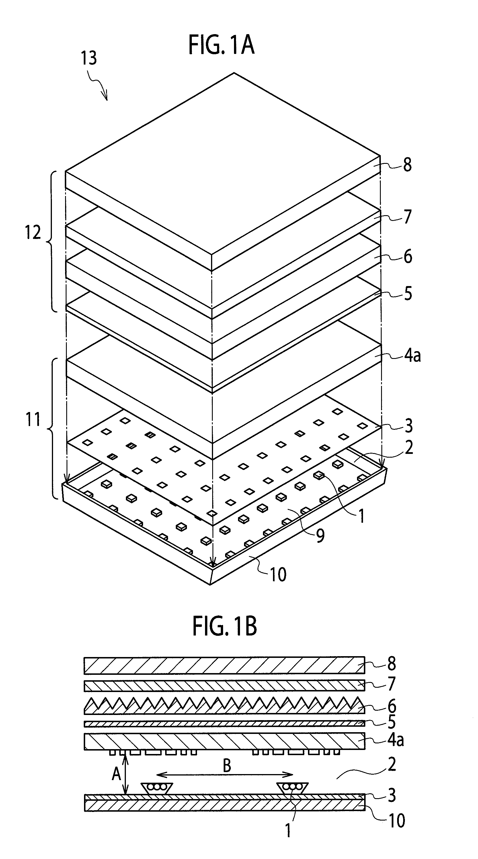
[0036]As shown in FIG. 1A, a non-self-luminous display device 13 includes a surface light source unit 11 and a non-self-luminous display unit 12 as an object to be illuminated by the surface light source unit 11. The surface light source unit 11 is used as an illuminating unit in the non-self-luminous display device 13.

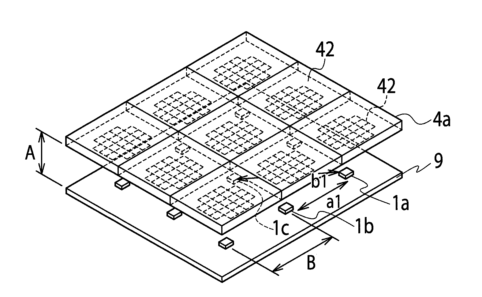
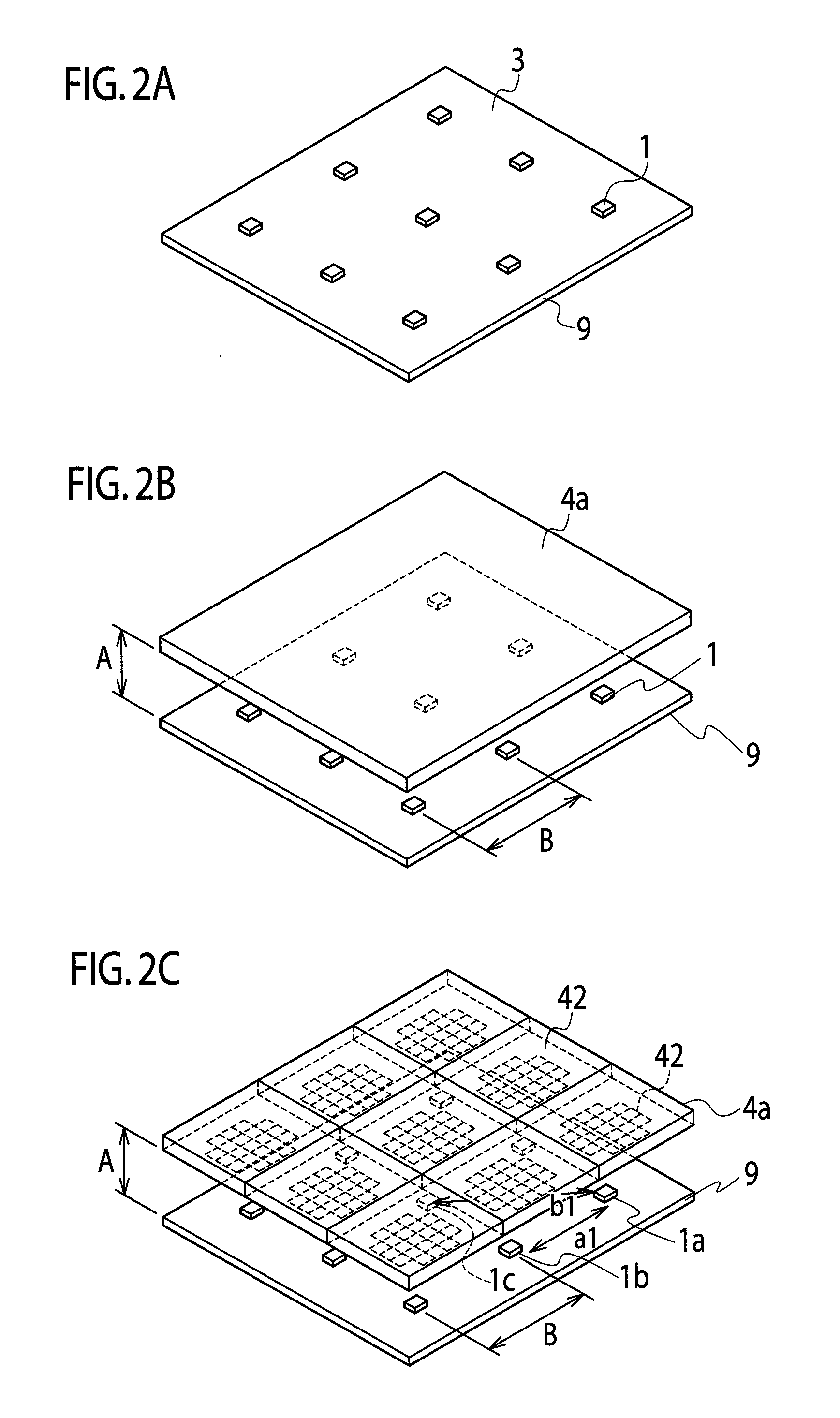
[0037]The surface light source unit 11 includes a plurality of LEDs 1, a light mixing chamber 2 accommodating the LEDs 1 (a plurality of point-like light sources), a reflecting member 3, a light quantity control member 4a for controlling a transmitted light quantity and a reflective light quantity with respect to the light quantity emitted from the respective LEDs 1 and a chassis 10 consisting primarily of aluminum and having a backside inner wall to which the LEDs 1 are attached and a lateral inner wall succeeding to the backside inner wall. In operation, the surface light source unit 11 is adapted so as to illuminate the non-self-luminous display unit ...


PUM

PropertyMeasurementUnit
hazeaaaaaaaaaa
hazeaaaaaaaaaa
circumferenceaaaaaaaaaa

Abstract

A light quantity control member includes a light diffusion part formed by light diffusion members for diffusing light from a LED. The light diffusion part includes a first rectangular area positioned at the center of light flux from the LED and second rectangular areas positioned around the first rectangular area. The first rectangular area has an occupied area of the light diffusion members larger than any other second rectangular areas. If respective distances between a first center of the first rectangular area and respective second centers of the second rectangular areas are equal to each other, the occupied areas of the diffusion members of the second diffusion areas become equal to each other. The longer the distance between the first center of the first rectangular area and the second center of the second rectangular area gets, the smaller the occupied area of the light diffusion members of the second rectangular area becomes.

Description

BACKGROUND OF THE INVENTION[0001]1. Field of the Invention[0002]The present invention relates to a light quantity control member of a surface light source unit used in a non-self-luminous display device. More particularly, the invention relates to a light quantity control member of a surface light source unit using a point-like light source, such as LED (Light Emitting Diode), a surface light source unit using the above light quantity control member and a display device using the above surface light source unit.[0003]2. Description of the Related Art[0004]Conventionally, there is proposed a non-self-luminous display device, as typified by a liquid crystal display device. In this non-self-luminous display device, a surface light source unit (i.e. a backlight unit) is arranged on the backside of a liquid crystal display device, for illuminating it. As one of the conventional surface light source units, there is known a so-called “inland-type” surface light source unit which includes a...

Claims


Application Information

Patent Timeline
Patent Type & Authority Applications(United States)
IPC IPC(8): G02F1/13357F21V11/00F21V7/00
CPCG02F1/133606G02F2001/133607G02B5/0278G02B5/0215G02F1/133607
Inventor SEGAWA, MASARU
Owner JVC KENWOOD CORP A CORP OF JAPAN
Why Eureka
Try Eureka