
Display Panel and Display Device Using the Same

a display device and display panel technology, applied in the direction of instruments, static indicating devices, etc., can solve the problems of inability to implement a full-screen display, limited screen size, and difficulty in designing the screen, so as to achieve uneven luminance, reduce the amount of current needed, and reduce the effect of screen siz

Active Publication Date: 2022-05-05
LG DISPLAY CO LTD
View PDF0 Cites 0 Cited by
  • Summary
  • Abstract
  • Description
  • Claims
  • Application Information

AI Technical Summary

Benefits of technology

This patent describes a method to improve image quality on a screen by using different voltages to drive the pixels in different areas of the screen. By setting different voltages for the low pixel density areas and the high pixel density areas, the method ensures that all pixels are operating in their saturation region, resulting in uniform luminance across the entire screen and improved image quality. Additionally, this method reduces power consumption and improves picture quality.

Problems solved by technology

A front camera of the smartphone restricts a screen design, making it difficult to design the screen.
In order to reduce a space occupied by the camera, a screen design including a notch or punch hole has been adopted in the smartphone, but the screen size is still limited due to the camera, making it impossible to implement a full-screen display.
A pixel area of a low PPI may have a lower luminance compared to a pixel region of a high PPI, which may cause an increase of the amount of current necessary to drive light emitting elements in pixels with the low PPI.
In this case, a transistor to drive a light emitting element operates in a linear area, resulting in uneven luminance in the low PPI area, even with small variations in source-drain voltage of the transistor, and thus image quality may deteriorate.

Method used


Image

  • Display Panel and Display Device Using the Same
  • Display Panel and Display Device Using the Same
  • Display Panel and Display Device Using the Same

Examples


Embodiment Construction

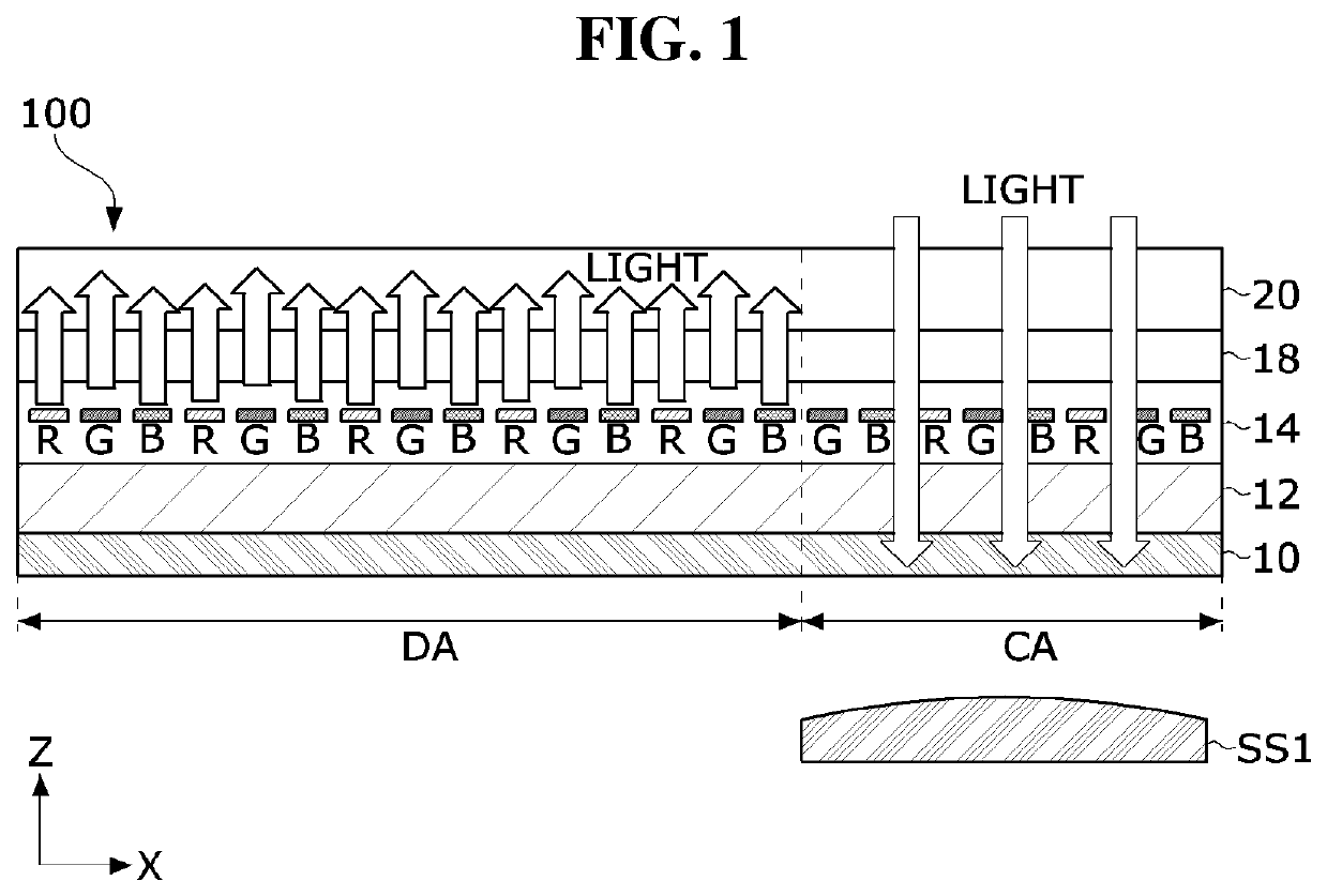
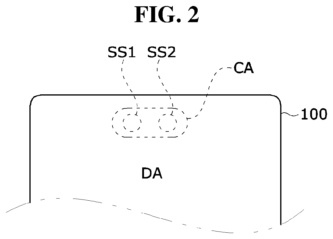
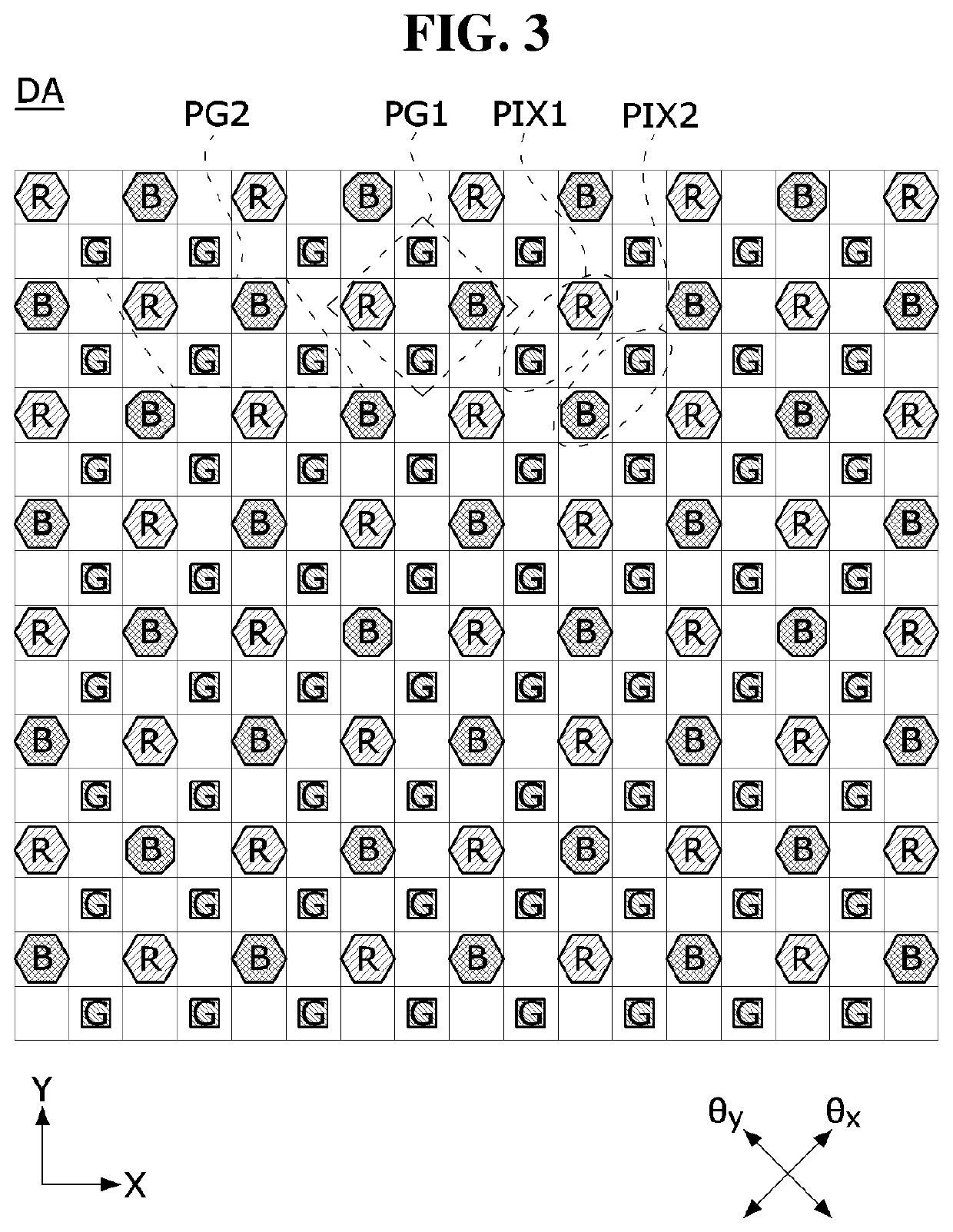
[0029]The advantages and features of the present disclosure and methods for accomplishing the same will be more clearly understood from embodiments described below with reference to the accompanying drawings. However, the present disclosure is not limited to the following embodiments but may be implemented in various different forms. Rather, the present embodiments will make the disclosure of the present disclosure complete and allow those skilled in the art to completely comprehend the scope of the present disclosure. The present disclosure is only defined within the scope of the accompanying claims.

[0030]The shapes, sizes, ratios, angles, numbers, and the like illustrated in the accompanying drawings for describing the embodiments of the present disclosure are merely examples, and the present disclosure is not limited thereto. Like reference numerals generally denote like elements throughout the present specification. Further, in describing the present disclosure, detailed descrip...


PUM

PropertyMeasurementUnit
DAaaaaaaaaaa
areaaaaaaaaaaa
voltageaaaaaaaaaa

Abstract

The present disclosure relates to a display panel and a display device using the same, and includes a first pixel area in which pixels connected to a first cathode electrode are disposed, and a second pixel area in which pixels connected to a second cathode electrode are disposed. A data voltage of pixel data to be written to a pixel in the second pixel area is applied to a first gate electrode of a driving element disposed in the second pixel area. A compensation voltage for increasing the luminance of the second pixel area is applied to the gate electrode of the driving element.

Description

CROSS-REFERENCE TO RELATED APPLICATION[0001]This application claims priority to and the benefit of Republic of Korea Patent Application No. 10-2020-0143009, filed Oct. 30, 2020, the disclosure of which is hereby incorporated herein by reference in its entirety.BACKGROUND1. Field[0002]The present disclosure relates to a display panel and a display device using the same.2. Discussion of Related Art[0003]Electroluminescent display devices are roughly classified into inorganic light emitting display devices and organic light emitting display devices depending on the material of an emission layer. The organic light emitting display device of an active matrix type includes an organic light emitting diode (hereinafter, referred to as “OLED”) that emits light by itself, and has an advantage in that the response speed is fast and the luminous efficiency, luminance, and viewing angle are large. In the organic light emitting display device, the OLED is formed in each pixel. The organic light e...

Claims


Application Information

Patent Timeline
Patent Type & Authority Applications(United States)
IPC IPC(8): G09G3/3233
CPCG09G3/3233G09G2320/0233G09G2300/043G09G3/3208G09G3/2074G09G2330/021H10K59/12H10K50/82G09G2300/0426G09G2340/0407G09G2320/0686G09G3/3258H10K59/121H10K59/131
Inventor LEE, DONG GUNJUNG, BO YUN
Owner LG DISPLAY CO LTD
Learn More