
Backlight system and liquid crystal display device using the same

a backlight system and liquid crystal display technology, applied in the direction of illuminated signs, display means, instruments, etc., can solve the problems of low efficiency in light use, method suffers from color breakage, and filter loses approximately 23 of light, so as to achieve improved efficiency in use, reduce luminance unevenness and color unevenness between areas within the display screen.

Inactive Publication Date: 2014-12-30
SHARP KK +1
View PDF9 Cites 0 Cited by
  • Summary
  • Abstract
  • Description
  • Claims
  • Application Information

AI Technical Summary

Benefits of technology

The present invention describes a way to create a backlight system that can focus different colored light beams onto different parts of a display screen, resulting in more efficient use of light and better quality full-color display. This can also reduce unevenness in brightness and color between different parts of the screen, leading to a higher-quality display. The invention also addresses the issue of thickness, making the backlight system more compact and efficient.

Problems solved by technology

However, since each of the R, G, and B color filters transmits light of wavelengths in its corresponding wavelength range and absorbs light of wavelengths in the other wavelength ranges, such a liquid crystal display device using color filters loses approximately ⅔ of the light and therefore has a low level of efficiency in the use of light.
Although there is a color-filter-free full-color display method called a field sequential color method, this method suffers from color breakup.
Note, however, that Patent Literature 1 does not exclude provision of a color filter for preventing colors from being undesirably mixed due to light leakage when the color separation is below the ideal.

Method used


Image

  • Backlight system and liquid crystal display device using the same
  • Backlight system and liquid crystal display device using the same
  • Backlight system and liquid crystal display device using the same

Examples


examples

[0132]The following shows results specifically verified by using examples and comparative examples. However, the present invention is not to be limited solely to the following examples.

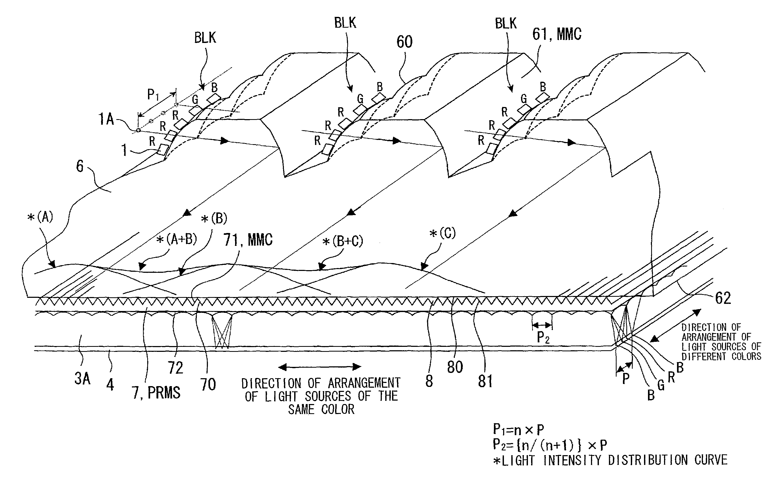
[0133]As an example of the present invention, a backlight system of an embodiment shown in (a) of FIG. 7 was manufactured by way of trial. The backlight system included an array of light sources 1 each constituted by three LEDs that emit R, G, and B light at dominant wavelengths, respectively. With light supplied from 3×3 blocks of the light source array along the direction of depth normal to the surface of (a) of FIG. 7 and along the horizontal direction across (a) of FIG. 7, a spatial luminance distribution of light exiting through the upper surfaces of microlenses was measured by a luminance chromaticity uniformity measuring apparatus (manufactured by Topcon Technohouse Corporation; UA-1000).

[0134]Each of the R, G, and B light sources 1 was constituted by a luminous point 10 and a focusing lens sys...


PUM

PropertyMeasurementUnit
vertex angleaaaaaaaaaa
refractive indexaaaaaaaaaa
thicknessaaaaaaaaaa

Abstract

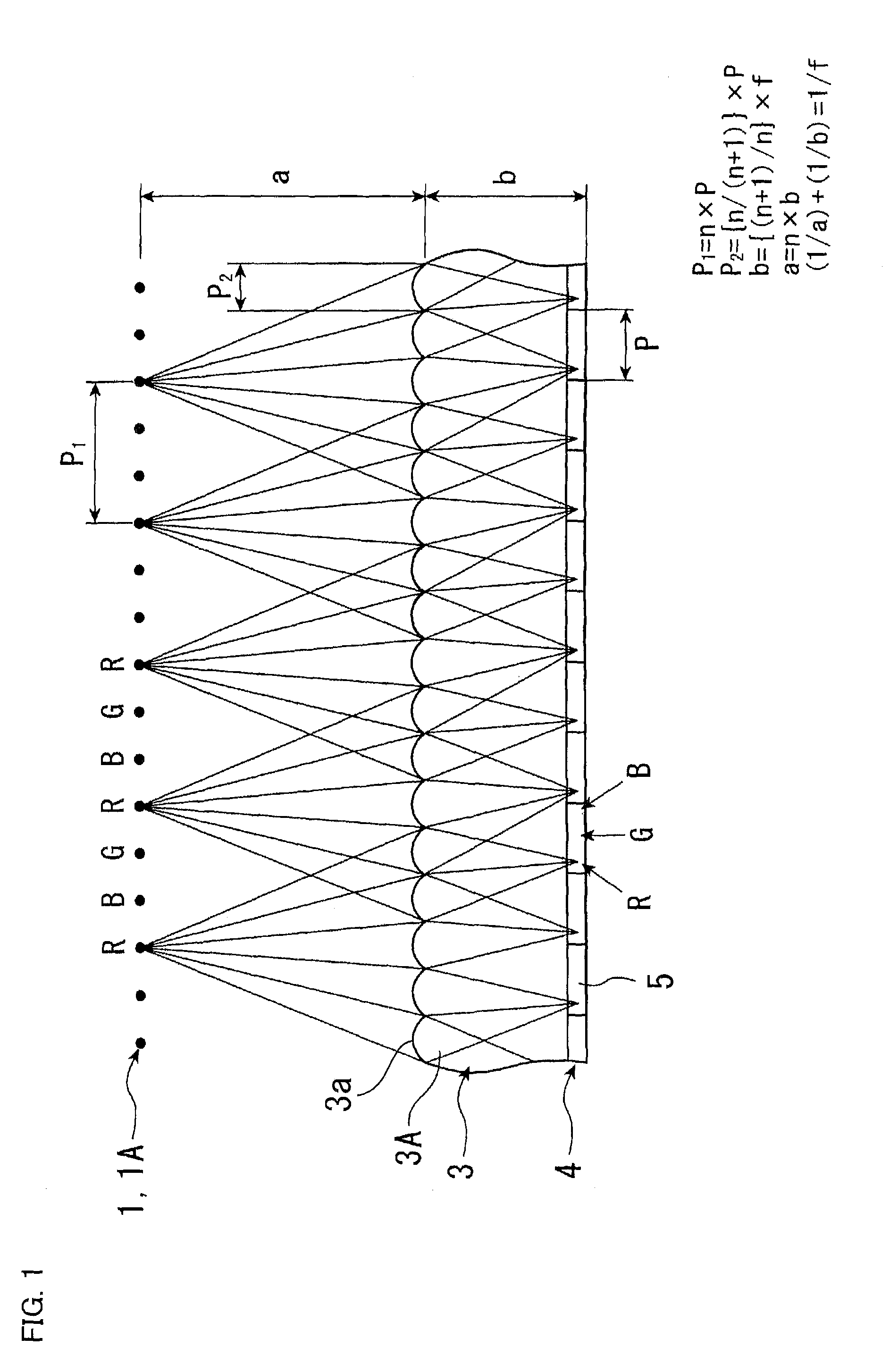
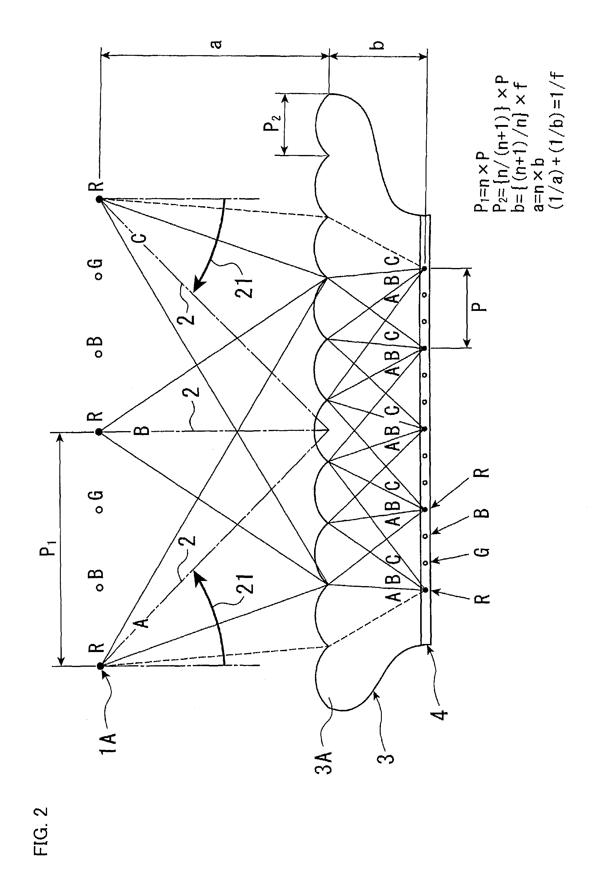
A backlight system includes: a light-emitting section (1) having a plurality of light sources that emit beams of light at different dominant wavelengths from one another; and an imaging optical system (3) including a plurality of microlenses (3a) that focus beams of light emitted from the light-emitting section (1), the backlight system irradiating a liquid crystal panel with beams of light having passed through the imaging optical system (3), the liquid crystal panel including a plurality of pixels arrayed at a predetermined pitch from each other, on the assumption that the pitch at which the pixels are arrayed is denoted as P and the imaging optical system (3) has an imaging magnification of (1 / n), the light sources (1) being arrayed at a pitch (P1) given as P1=n×P, the microlenses (3a) being arrayed at a pitch (P2) given as P2=(n / (n+1))×P.

Description

TECHNICAL FIELD[0001]The present invention relates to backlight systems and liquid crystal display devices using such backlight systems and, more particularly, to a backlight system that focuses different colors of light onto the back surfaces of their corresponding picture elements, into which each pixel of a transmissive liquid crystal display element has been divided according to color, and to a liquid crystal display device that carries out a full-color display by using such a backlight system and such a liquid crystal display element.BACKGROUND ART[0002]Conventionally, a liquid crystal display device that carries out a full-color display achieves a full-color display by dividing each pixel of a transmissive liquid crystal display element into three picture elements, attaching red (R), green (G), and blue (B) color filters to the three picture elements, respectively, irradiating the three picture elements with white light from a backlight, and controlling, according to a signal ...

Claims


Application Information

Patent Timeline
Patent Type & Authority Patents(United States)
IPC IPC(8): G02F1/1335
CPCG02F1/133606G02F2001/133607G02F1/133607
Inventor UCHIDA, TATSUOSUZUKI, YOSHITOKAWAKAMI, TOHRUSEKIYA, KAZUONISHIZAWA, MASAHIROISHINABE, TAKAHIROKATAGIRI, BAKUHASHIMOTO, YOSHIHIROISHIHARA, SHOICHIKOZAKI, SHUICHIISHII, YUTAKA
Owner SHARP KK
Learn More