Display apparatus

a technology of display apparatus and display plate, which is applied in the field of display plate, can solve the problems of affecting the appearance of the display plate, so as to prevent the damage prevent the fluctuation of the optical plate, and reduce the effect of luminan

Inactive Publication Date: 2018-05-01
SAKAI DISPLAY PROD
View PDF16 Cites 0 Cited by
  • Summary
  • Abstract
  • Description
  • Claims
  • Application Information

AI Technical Summary

Benefits of technology

[0010]The display apparatus disclosed is used in a state in which the higher peripheral wall among the peripheral walls of the backlight box faces down, and the bottom stands in a vertical direction. In this case, the optical sheet is held so as to be hung on the hooking parts provided on the peripheral end face of the lower peripheral wall. Since the peripheral end faces of the backlight box are inclined with respect to the bottom at a prescribed angle, peripheral edge parts other than one edge part corresponding to the hooking parts among the peripheral edge parts of the optical sheet are pressed and come into close contact with the inclined diffusion plate of the backlight box due to their own weight, to be stabilized. Thereby, it is possible to restrain an occurrence of the fluctuation in which the optical sheet moves in the direction perpendicular to the surface thereof.
[0020]According to the embodiment of the present invention, it is possible to suppress the fluctuation of the optical sheet in the thickness direction in the display apparatus. Thereby, it is possible to prevent sheet damage of the optical sheet, and problems such as luminance unevenness, or a decrease in luminance, while coping with a request for thinning and slimmed border.

Problems solved by technology

In a situation in which strong vibrations are applied during a vibration test, transportation, or the like, peripheral edges of the optical sheet are rubbed by the fluctuation thereof to cause sheet damage.
If there is sheet damage in the optical sheet, problems such as luminance unevenness, or a decrease in luminance may occur in the display apparatus.

Method used


Image

  • Display apparatus
  • Display apparatus
  • Display apparatus

Examples


embodiment 1

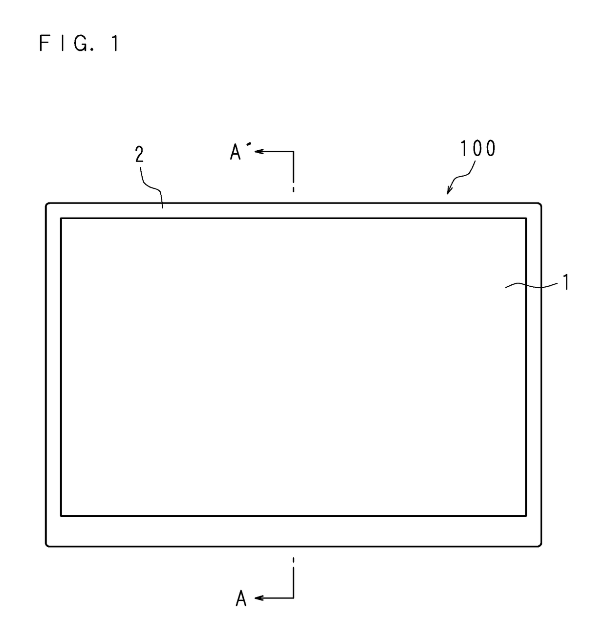
[0028]FIG. 1 is a front view illustrating an appearance of a display apparatus 100 according to Embodiment 1. The display apparatus 100 is formed by positioning and housing a liquid crystal panel 1 and other parts by a plurality of other chassis including a first chassis 2.

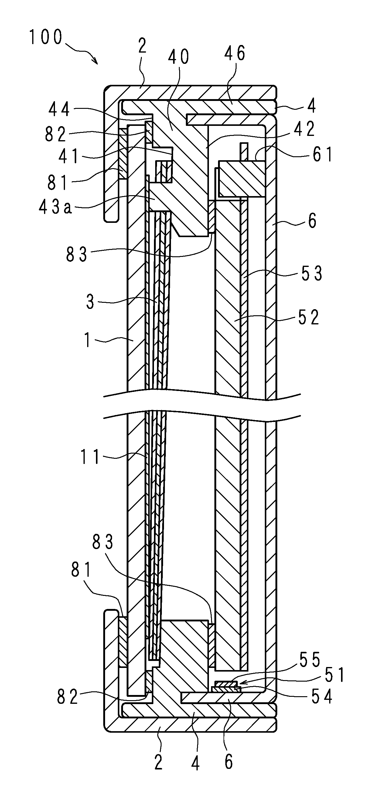
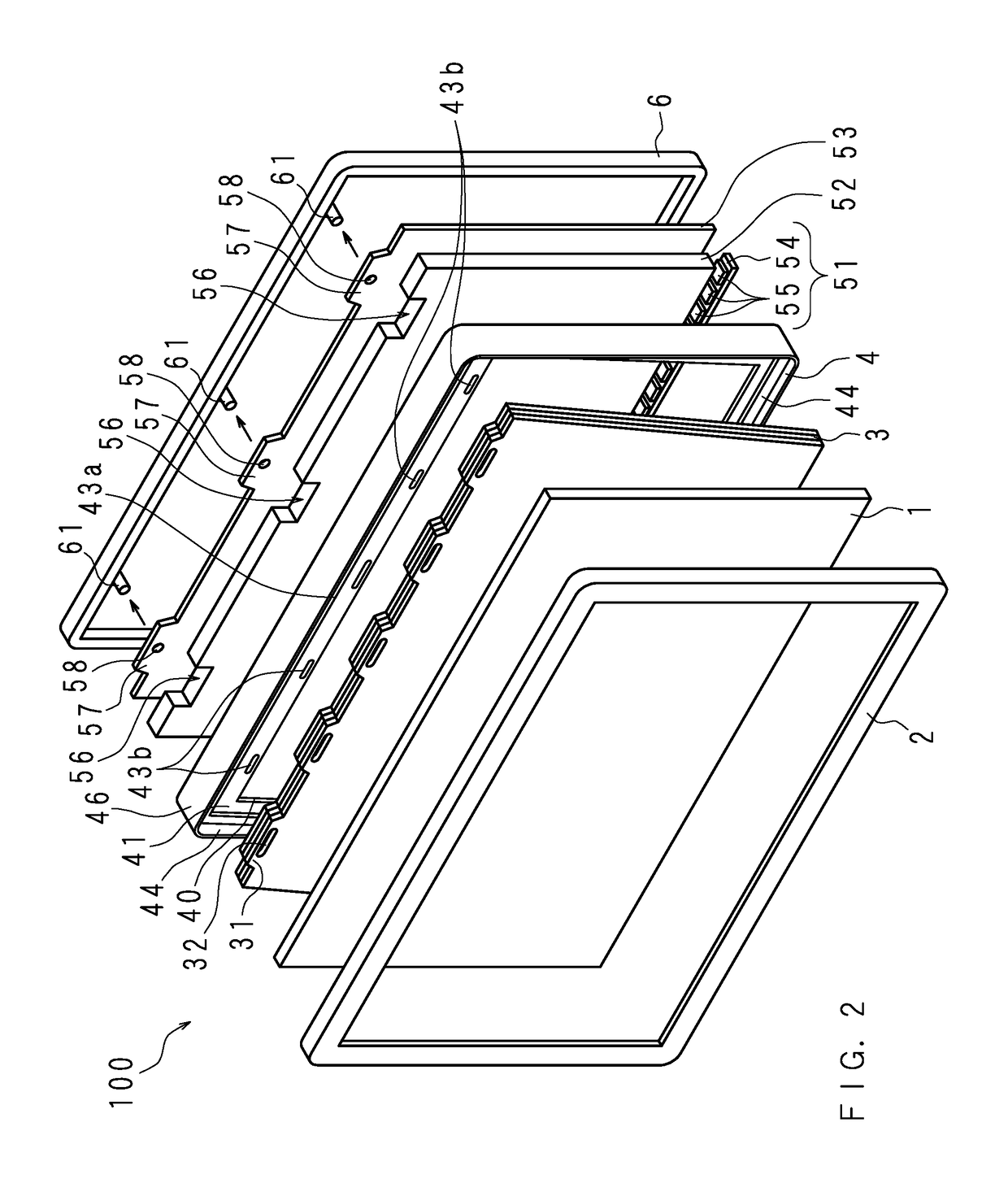
[0029]FIG. 2 is an exploded perspective view schematically illustrating main components included in the display apparatus 100 according to Embodiment 1, and FIG. 3 is a longitudinal-sectional view taken on line A-A′ of FIG. 1.

[0030]The display apparatus 100 includes the liquid crystal panel 1, the first chassis 2, an optical sheet 3, a second chassis 4, a light guide plate 52, a light source 51, a reflection sheet 53, and a third chassis 6.

[0031]The first chassis 2 is a rectangular-shaped frame body. The first chassis 2 includes a side plate of a rectangular and cylindrical shape, and a frame part of a hollow plate protruding inward from one end portion of the side plate, and has an L-shaped cross section.

[0032]Th...

embodiment 2

[0060]The structure of the second chassis 4 to prevent the optical sheet 3 from being fluctuated may be a structure as Embodiment 2 illustrated below. FIG. 5 is a perspective view schematically illustrating a second chassis 7 according to Embodiment 2, and FIG. 6 is a longitudinal-sectional view taken on line C-C′ of FIG. 5. FIG. 6 illustrates a cross section when cutting an edge part of a holding plate 70 of the second chassis 7 on one short side in the lateral direction. Further, a dashed line in FIG. 6 illustrates an outline of the cross section of the optical sheet 3 to be held.

[0061]The second chassis 7 may be used as a substitute for the second chassis 4 according to Embodiment 1 as it is. Therefore, the configuration of other main components of the display apparatus 100, and the relationship with the other main components of the second chassis 7 will not be described in detail.

[0062]The second chassis 7 is a frame body provided with a peripheral plate 76 at outer peripheral e...


PUM

PropertyMeasurementUnit
shapeaaaaaaaaaa
distanceaaaaaaaaaa
heightaaaaaaaaaa

Abstract

Provided is a display apparatus having a holding structure for an optical sheet capable of preventing wrinkles, bending, and sheet damage to the optical sheet in the display apparatus, and preventing defects such as irregular brightness and reduced brightness.A chassis for holding an optical sheet of a rectangular shape holds the peripheral edge part of the optical sheet at a holding surface of hollow rectangular shape, and has engaging parts to hold the optical sheet provided to stand at the edge part of one side of the holding surface. The holding surface is inclined or has a stepped protuberance formed, whereby the surface of the other region opposite of the end part of the one region on which the engaging parts is provided to stand is closer to the display panel than the surface of the one region of the holding surface within the height range of the engaging part, wherein the one region and the other region are present on the opposite side with respect to an opening of the holding surface.

Description

[0001]This application is the national phase under 35 U.S.C. § 371 of PCT International Application No. PCT / JP2013 / 080218 which has an International filing date of Nov. 8, 2013 and designated the United States of America.BACKGROUND OF THE INVENTION[0002]1. Field of the Invention[0003]The present invention relates to a display apparatus which displays an image using a liquid crystal panel. Particularly, the present invention relates to a display apparatus which has a holding structure of a sheet capable of preventing an occurrence of problems such as luminance unevenness, or a decrease in luminance due to wrinkles, deflection, damage, or the like of an optical sheet used in the display apparatus, while thinning the display apparatus.[0004]2. Description of Related Art[0005]A display apparatus using a liquid crystal panel is provided with an optical sheet for diffusing or collecting light emitted from a light source. The optical sheet is provided between the liquid crystal panel and t...

Claims


Application Information

Patent Timeline
Patent Type & Authority Patents(United States)
IPC IPC(8): G02F1/1333F21V8/00G02F1/1335
CPCG02F1/133308G02B6/002G02B6/0065G02B6/0068G02F1/133553G02F1/133528G02F2201/54G02F2001/133317G02F2001/133354G02B6/0088G02F1/133317G02F1/133354
Inventor MATSUMOTO, KOUJIKAWABATA, RYOTA
Owner SAKAI DISPLAY PROD
Why Eureka
Try Eureka