Projection lens and projection-type display apparatus
a projection lens and projection-type technology, applied in the field of projection lenses, can solve the problems of not meeting recent demand, speed of lens, and especially in the speed of lens, and achieve the effects of reducing cost, increasing the precision of light modulation devices, and faster and higher-performance projection lenses
- Summary
- Abstract
- Description
- Claims
- Application Information
AI Technical Summary
Benefits of technology
Problems solved by technology
Method used
Image

Examples
example 1
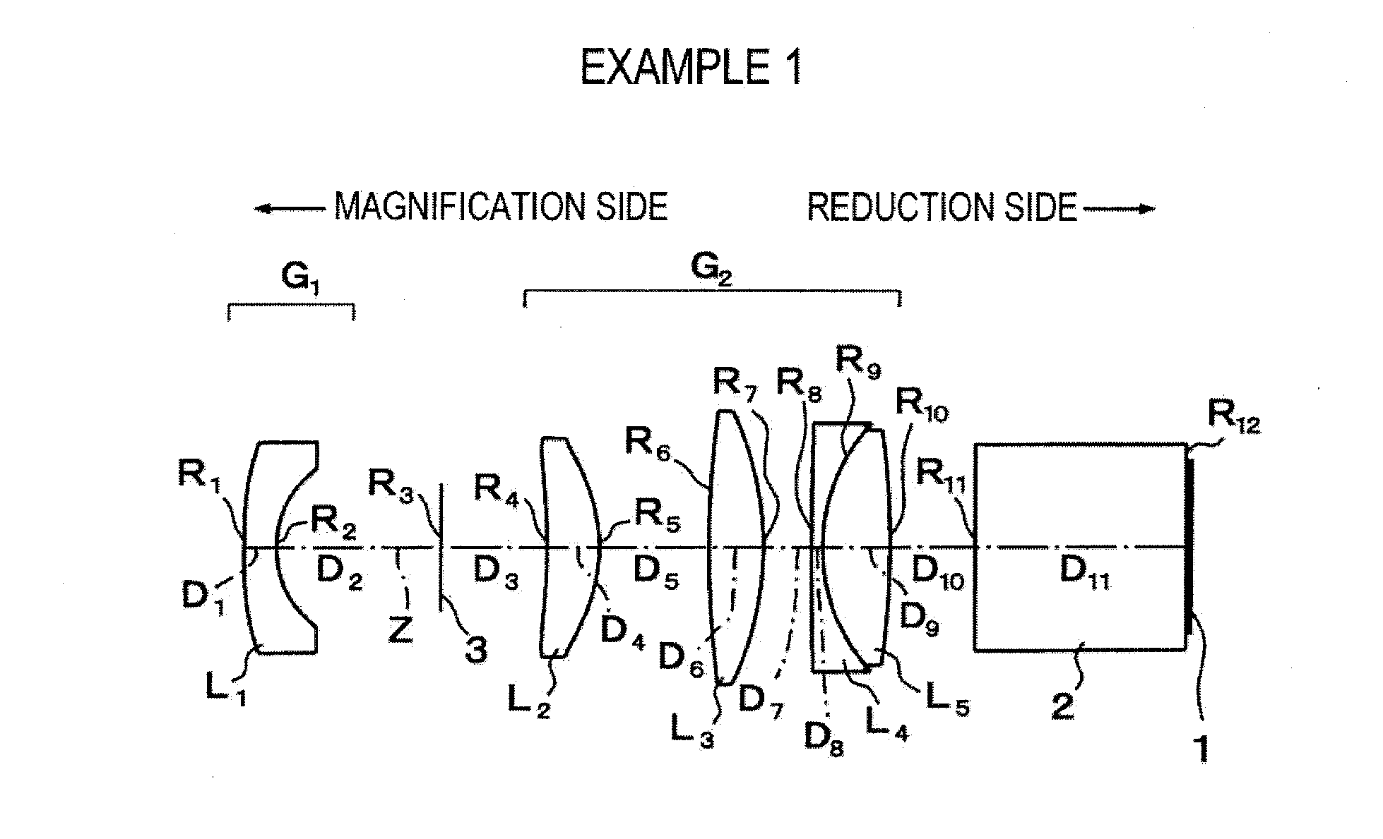
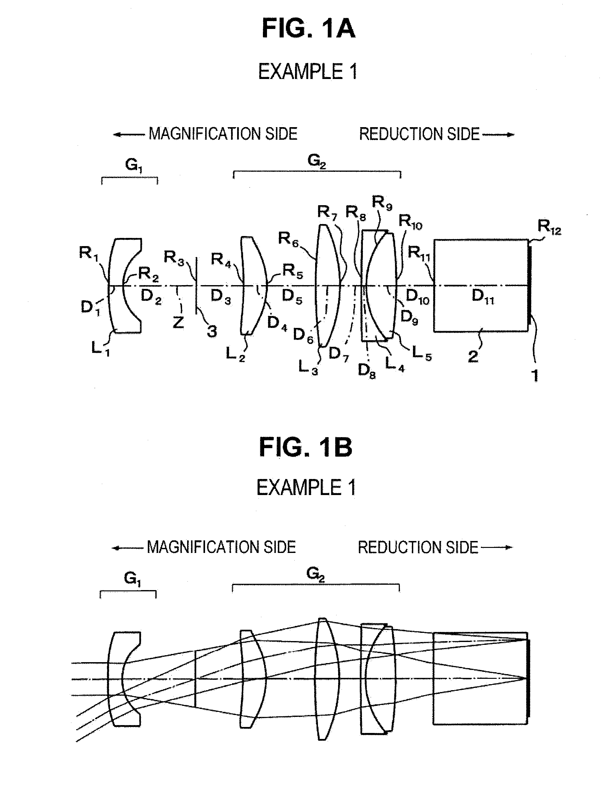
[0088]The projection lens according to Example 1 is configured as shown in FIG. 1. As described above, the projection lens is configured so that, in order from the magnification side, the first lens group G1, which has a negative refractive power, and the second lens group G2, which has a positive refractive power, are arranged. The projection lens is a fixed focus lens including a total of five lenses (first lens L1 to fifth lens L5), in which the aperture stop 3 is disposed between the first lens group G1 and the second lens group G2. In addition, the projection lens is configured to be telecentric on the reduction side. In addition, on the reduction side thereof, there are also arranged the glass block 2 mostly using a color synthesizing prism and the image display surface 1.
[0089]The first lens group G1 includes only the first lens L1 formed as a positive meniscus lens (based on the shape on the optical axis Z), made of plastic, of which a concave surface faces toward the reduct...
example 2
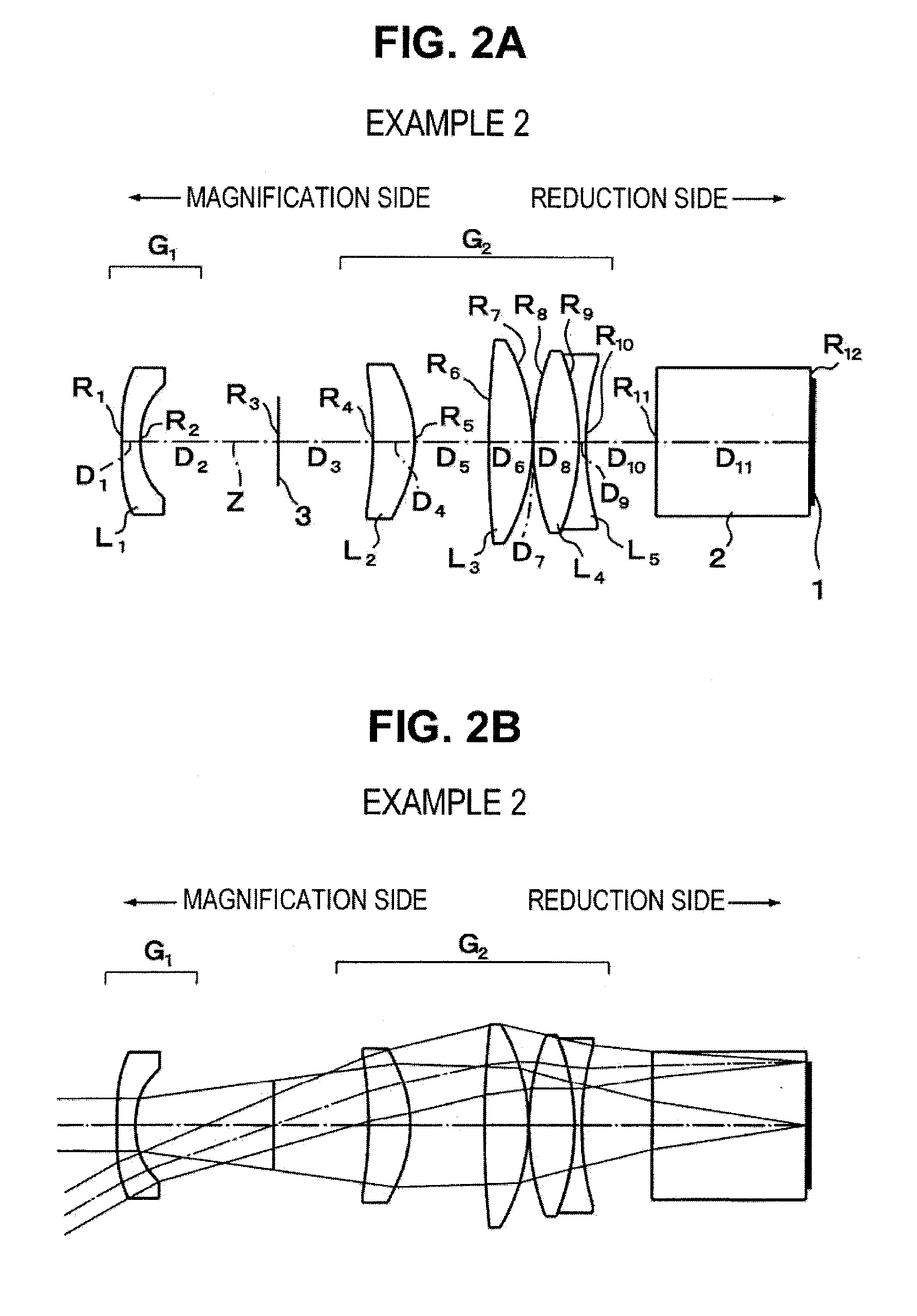
[0095]The projection lens according to Example 2 is configured as shown in FIG. 2. Specifically, the projection lens has substantially the same configuration as that of Example 1 mentioned above. However, there are differences in the following points. First, the first lens L1 constituting the first lens group G1 is formed in a biconcave shape on the optical axis Z. Second, in the second lens group G2, the fourth lens L4 is formed as a biconvex lens, and the fifth lens L5 is formed as a biconcave lens (which constitutes the single negative lens in the second lens group G2) (the fourth lens L4 and fifth lens L5 are cemented to each other similarly to Example 1).
[0096]In Example 2, the upper part of Table 2 shows radii of curvature R of the lens surfaces, center thicknesses of the lenses and air spaces D between the lenses, and refractive indices Nd and Abbe numbers νd of the lenses at the d-line. Further, the lower part of Table 2 shows respective constants K and A3 to A16 correspondi...
example 3
[0099]The projection lens according to Example 3 is configured as shown in FIG. 3. Specifically, the projection lens has substantially the same configuration as that of Example 1 mentioned above. However, there are differences in the following points. In the second lens group G2, the second lens L2 is formed in a biconvex shape on the optical axis Z, the fourth lens L4 is formed as a biconcave lens, and each of the fourth lens L4 and the fifth lens L5 is formed as each single lens (the lenses are not cemented to each other).
[0100]In Example 3, the upper part of Table 3 shows radii of curvature R of the lens surfaces, center thicknesses of the lenses and air spaces D between the lenses, and refractive indices Nd and Abbe numbers νd of the lenses at the d-line. Further, the lower part of Table 3 shows respective constants K and A3 to A16 corresponding to the respective aspheric surfaces.
TABLE 3FOCAL LENGTH F = 1.00SURFACERDNdνd 1*0.9490.1581.491057.6 2*0.3961.659 3 (APERTURE∞0.420STOP...
PUM
 Abstract
Description
Claims
Application Information
 - R&D Engineer
- R&D Manager
- IP Professional
- Industry Leading Data Capabilities
- Powerful AI technology
- Patent DNA Extraction
Browse by: Latest US Patents, China's latest patents, Technical Efficacy Thesaurus, Application Domain, Technology Topic.
© 2024 PatSnap. All rights reserved.Legal|Privacy policy|Modern Slavery Act Transparency Statement|Sitemap