Check patentability & draft patents in minutes with Patsnap Eureka AI!

Improved floating device for pipes

a floating device and pipe technology, applied in the direction of buoys, pipe laying and repair, route marking with anchored lightships, etc., can solve the problems of high manufacturing cost, complicated and time-consuming use of floating devices, and considerable space occupation

Inactive Publication Date: 2011-03-03
VALORE ITALA
View PDF4 Cites 5 Cited by
  • Summary
  • Abstract
  • Description
  • Claims
  • Application Information

AI Technical Summary

Benefits of technology

[0019]According to the invention and thanks to the particular structure with protrusions and slots formed in the opposite longitudinal edges of the substantially semi-tubular body of the floating elements, it is advantageously possible to achieve the desired broadening of the adjustment range of the pipe housing seat to be maintained in a floating condition by simply moving the floating elements towards or away from each other and without the need of mounting any adapter within the aforementioned seat.
[0024]Advantageously, the floating device of the invention allows to achieve the aforementioned first adjustment range of the transversal section of the pipe housing seat thanks to at least a partial interpenetration of the substantially semi-tubular bodies of the floating elements which thus define a housing seat defined by the intersection of the inner walls of the floating elements.
[0029]Advantageously, the floating device of the invention effectively holds the pipe in place in both the aforementioned mounting configurations of the floating elements and in both the aforementioned embodiments of the inner walls of the floating elements thanks to the presence of a plurality of contact surfaces between the pipe and the inner walls of the floating elements and thanks to the presence of the protrusions extending from the longitudinal edges of the substantially semi-tubular body of the floating elements, which protrusions serve as abutment elements adapted to prevent unwanted lateral movements of the pipe in all the adjustment conditions.

Problems solved by technology

Although the floating devices of this type are substantially meeting the purpose, they have the significant drawback of being unable to adapt themselves to different pipe diameters with the consequent need of having to purchase and keep on storage as many sizes of floating devices as the type of pipes used in the various transport applications, with the consequent high manufacturing costs and considerable use of space.
Although this second type of floating devices allows to accomplish a partial adaptation to several different diameters of the pipe with a same size of the floating elements, such an adaptation is limited within a narrow adjustment range and is generally comprised in the range between 10 and 150 mm, so that the need of anyhow keeping on storage a certain number of floating elements of various sizes in the warehouse, clearly in addition to several sizes of adapters, is not entirely eliminated.
In addition, the use of these floating devices is more complicated and time-consuming since whenever the size of a pipe changes, more suitable adapters are to be mounted, optionally removing the adapters already installed for a different pipe size, before using the floating devices.
Since the adapters are installed on site, the adapters may be lost in the water hence extending the assembling times and increasing the costs.

Method used


Image

  • Improved floating device for pipes
  • Improved floating device for pipes
  • Improved floating device for pipes

Examples


Embodiment Construction

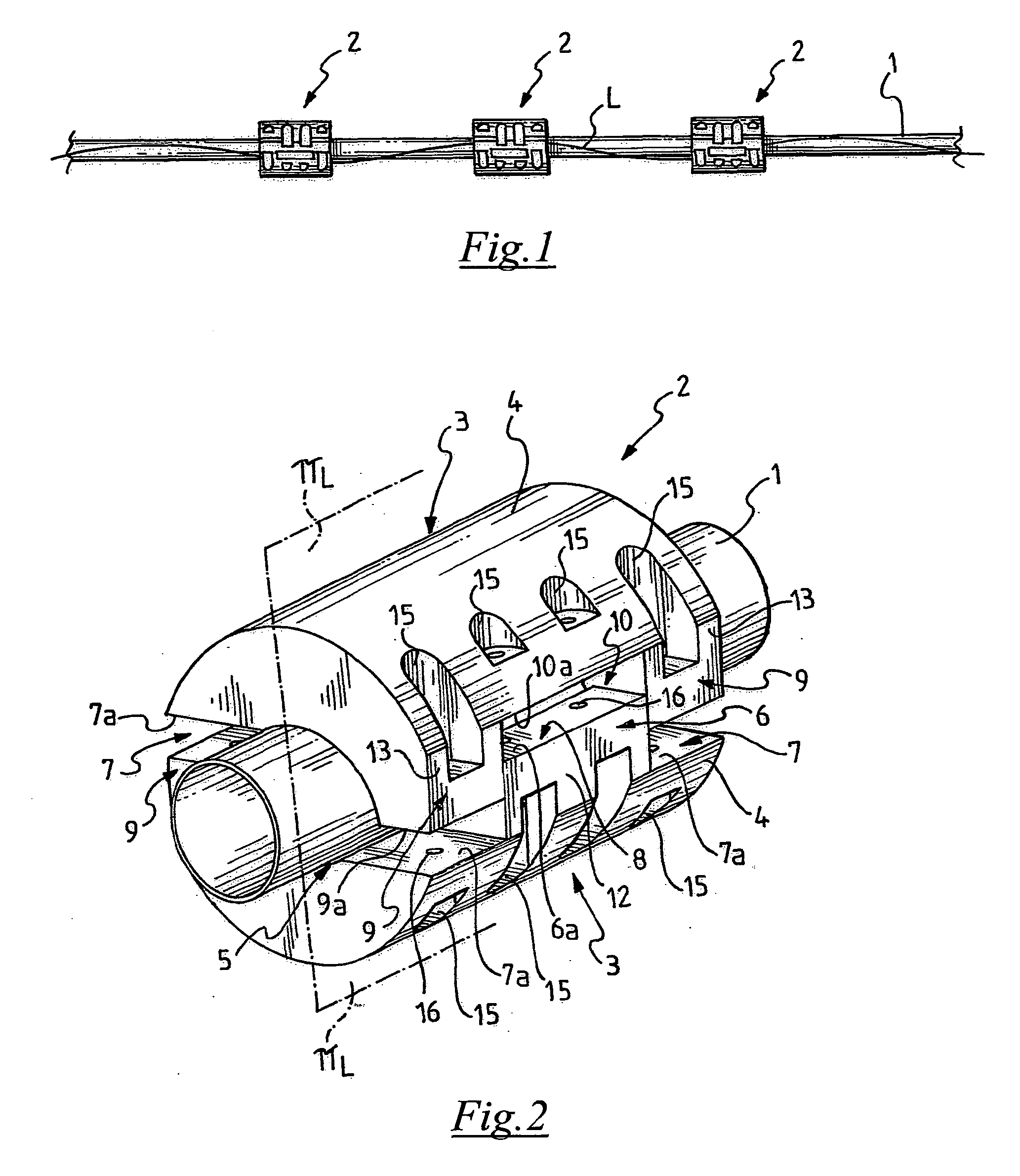
[0053]With reference to FIG. 1, a pipe for transporting solid substances, for example a flexible pipe made of plastic material for transporting a suspension or “slurry” of solid dredge material drained onshore, maintained in a floating condition in water, for example in the sea the free surface of which is indicated at L in FIG. 1, by means of a plurality of floating devices 2 according to the invention, is generally indicated at 1.

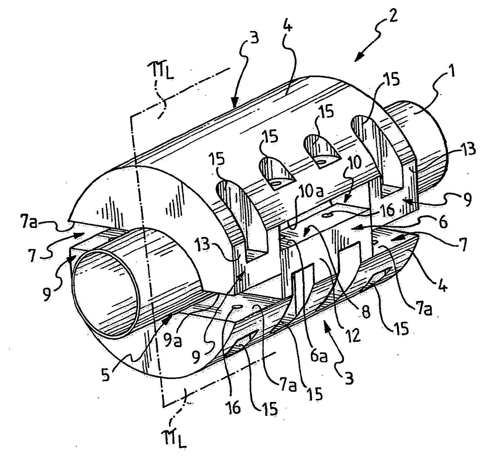
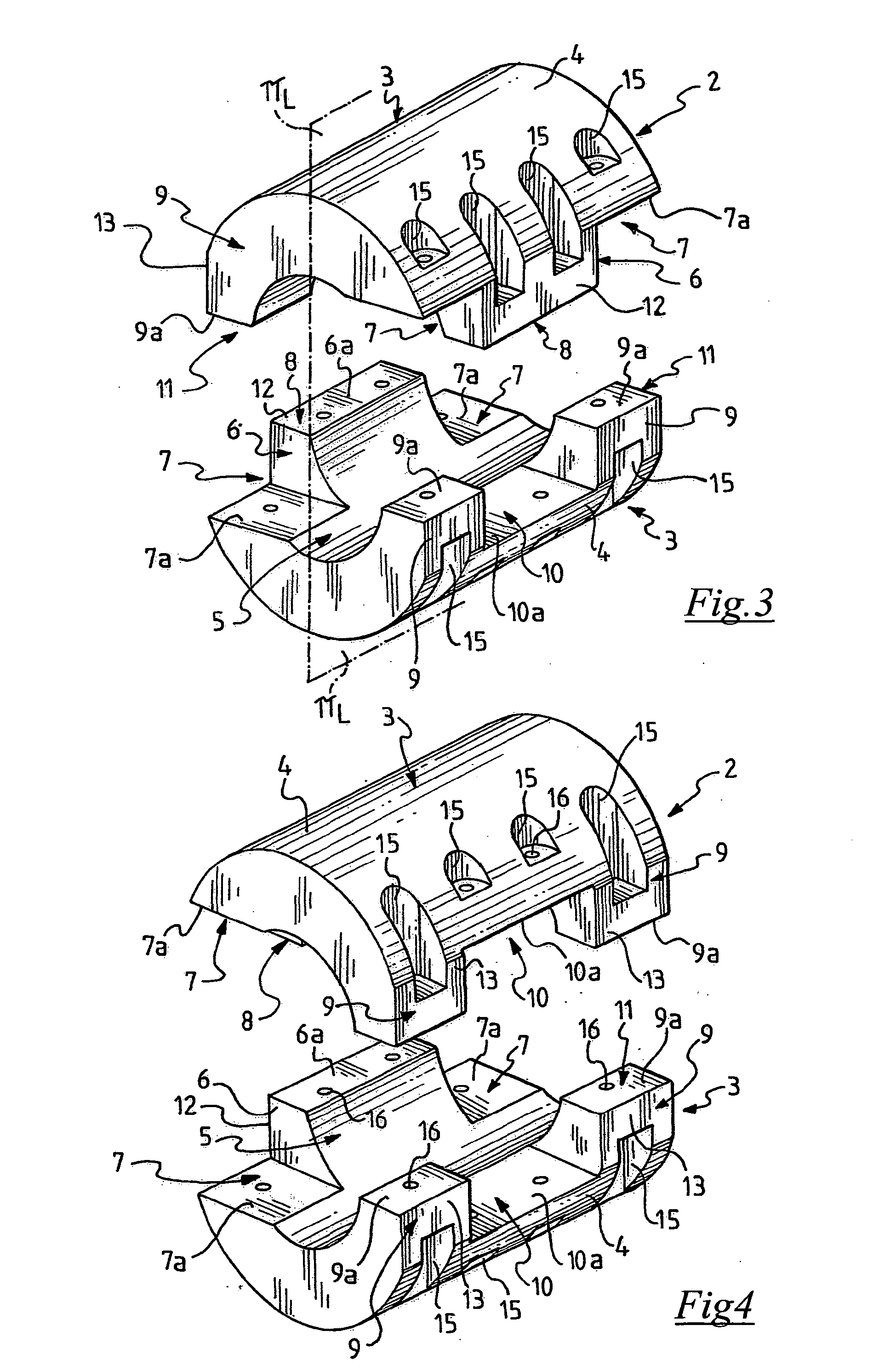
[0054]In a first preferred embodiment of the floating device 2 illustrated in FIGS. 2-10, each floating device 2 comprises a pair of floating elements 3, structurally identical to each other, each comprising a substantially semi-tubular body, indicated at 4.

[0055]The floating elements 3 are removably associable to each other so as to define a seat 5 for housing the pipe 1 whose transversal section can be advantageously radially adjusted in a very easy manner, as will be described in more detail hereinafter, so as to be capable of housing pipes having an o...


PUM


Abstract

A floating device (2, 102) for pipes (1) is described comprising at least two floating elements (3) each comprising a substantially semi-tubular body (4) and removably associable so as to define a pipe (1) housing seat (5), wherein the substantially semi-tubular body (4) of the floating elements (3) comprises at least a first protrusion (6) and at least a first slot (7) at a first longitudinal edge (8) thereof and at least a second protrusion (9) and at least a second slot (10) at a second opposite longitudinal edge (11) thereof; advantageously, the protrusions (6, 9) are substantially aligned with the slots (7, 10) at opposite parts with respect to a longitudinal centreline plane (TXL) of the floating element (3) so as to allow at least a partial interpenetration of the substantially semi-tubular bodies (4) of the floating elements (3).

Description

FIELD OF THE INVENTION[0001]The present invention relates to the field of floating devices used to maintain in a floating condition pipes or ducts for transporting solid, liquid or gaseous substances in the sea, rivers, lakes or other water basins.[0002]More particularly, the present invention relates to a floating device for pipes comprising at least two floating elements each comprising a substantially semi-tubular body and removably associable so as to define a pipe housing seat.[0003]The invention also relates to a floating element which may be used for realising a floating device for pipes, comprising a substantially semi-tubular body provided with at least one seat for housing a respective fixing device for removably associating the floating element to at least an additional floating element of the device.PRIOR ART[0004]In the field of transporting solid, liquid or gaseous substances in a sea, river or lake environment, the need often arises of ensuring that the pipes used for...

Claims


Application Information

Patent Timeline
IPC IPC(8): F16L1/24F16L3/10
CPCF16L3/1041F16L1/24
Inventor BENEDETTI, DAVIDE
Owner VALORE ITALA
Features
  • R&D
  • Intellectual Property
  • Life Sciences
  • Materials
  • Tech Scout
  • Unparalleled Data Quality
  • Higher Quality Content
  • 60% Fewer Hallucinations
Learn More