

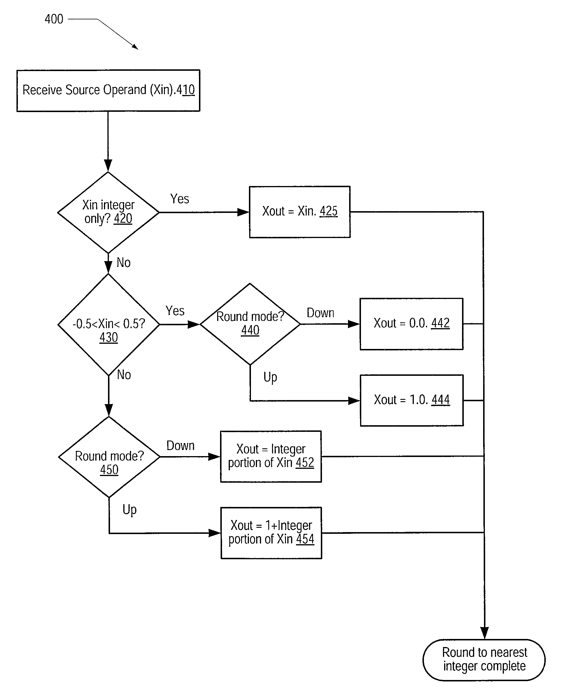
Method for floating point round to integer operation
a floating point round and integer technology, applied in computing, computation using denominational number representation, instruments, etc., can solve the problem of increasing the overall latency of such implementations
- Summary
- Abstract
- Description
- Claims
- Application Information
AI Technical Summary
Benefits of technology
Problems solved by technology
Method used
Image

Examples
Embodiment Construction
[0023]Generally speaking, the invention herein described may be implemented through any of a variety of processing devices including a central processing unit (CPU), graphics processing unit (GPU), floating point execution unit (FPU) or a portion of any of the above units. In the discussions that follow, a general-purpose processor core that includes at least one FPU will be used as a non-limiting example. Various other embodiments are possible and are contemplated.
Overview of Processor Core
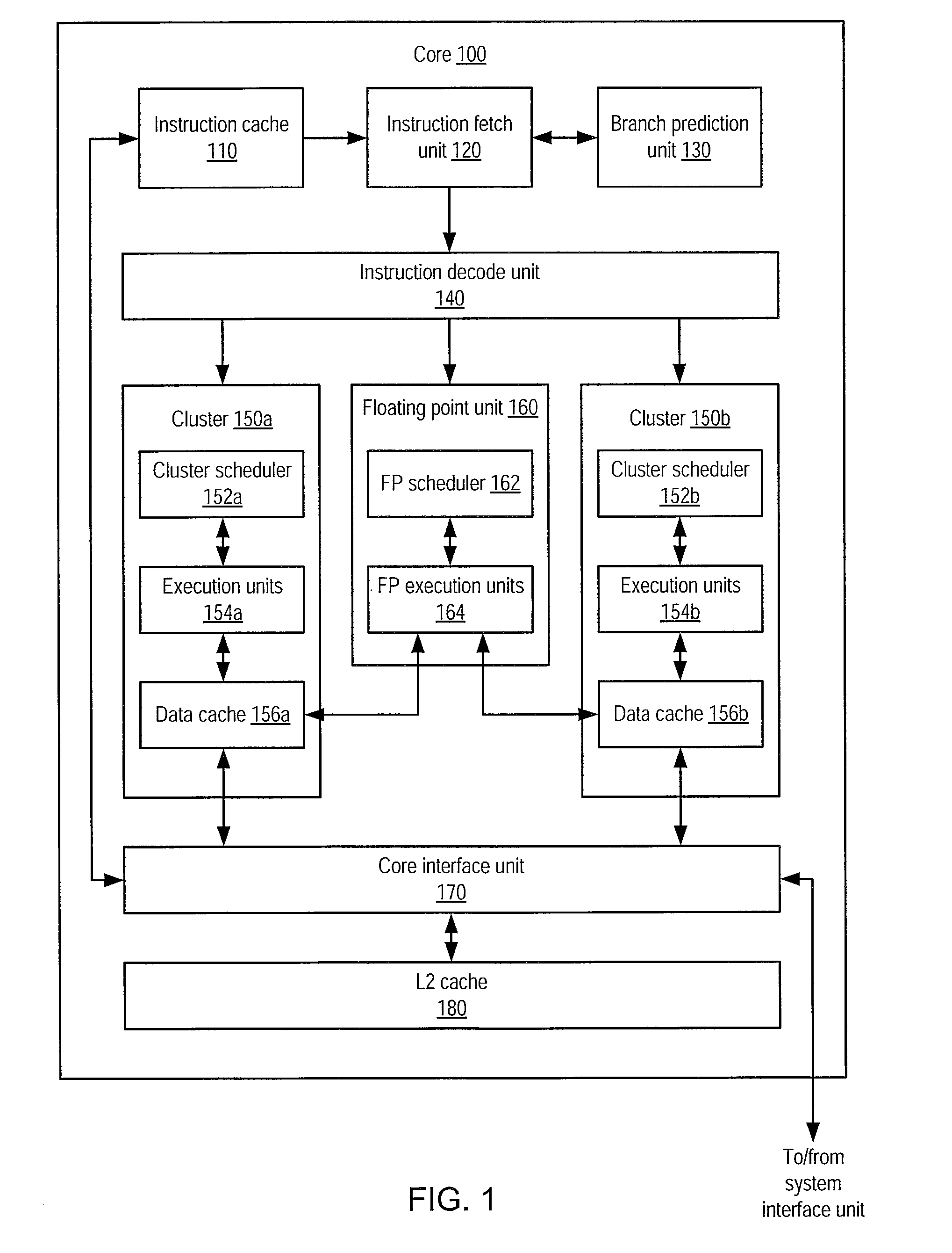
[0024]FIG. 1 illustrates one embodiment of a processor core 100. Generally speaking, core 100 may be configured to execute instructions that may be stored in a system memory that is directly or indirectly coupled to core 100. Such instructions may be defined according to a particular instruction set architecture (ISA). For example, core 100 may be configured to implement a version of the x86 ISA, although in other embodiments core 100 may implement a different ISA or a combination of ISAs.
[0025]I...
PUM
 Abstract
Description
Claims
Application Information