
Digital amplifier with improved performance

a digital amplifier and performance technology, applied in the field of digital amplifiers, can solve the problems of unreasonable clock rate, noise-shaping filter reducing the required resolution of input signals, and limitations of this topology for audio cds, so as to improve linearity, improve the effect of linearity and reduce the total harmonic distortion

Inactive Publication Date: 2003-07-15
GROVES JR WILLIAM HARRIS +1
View PDF12 Cites 53 Cited by
  • Summary
  • Abstract
  • Description
  • Claims
  • Application Information

AI Technical Summary

Benefits of technology

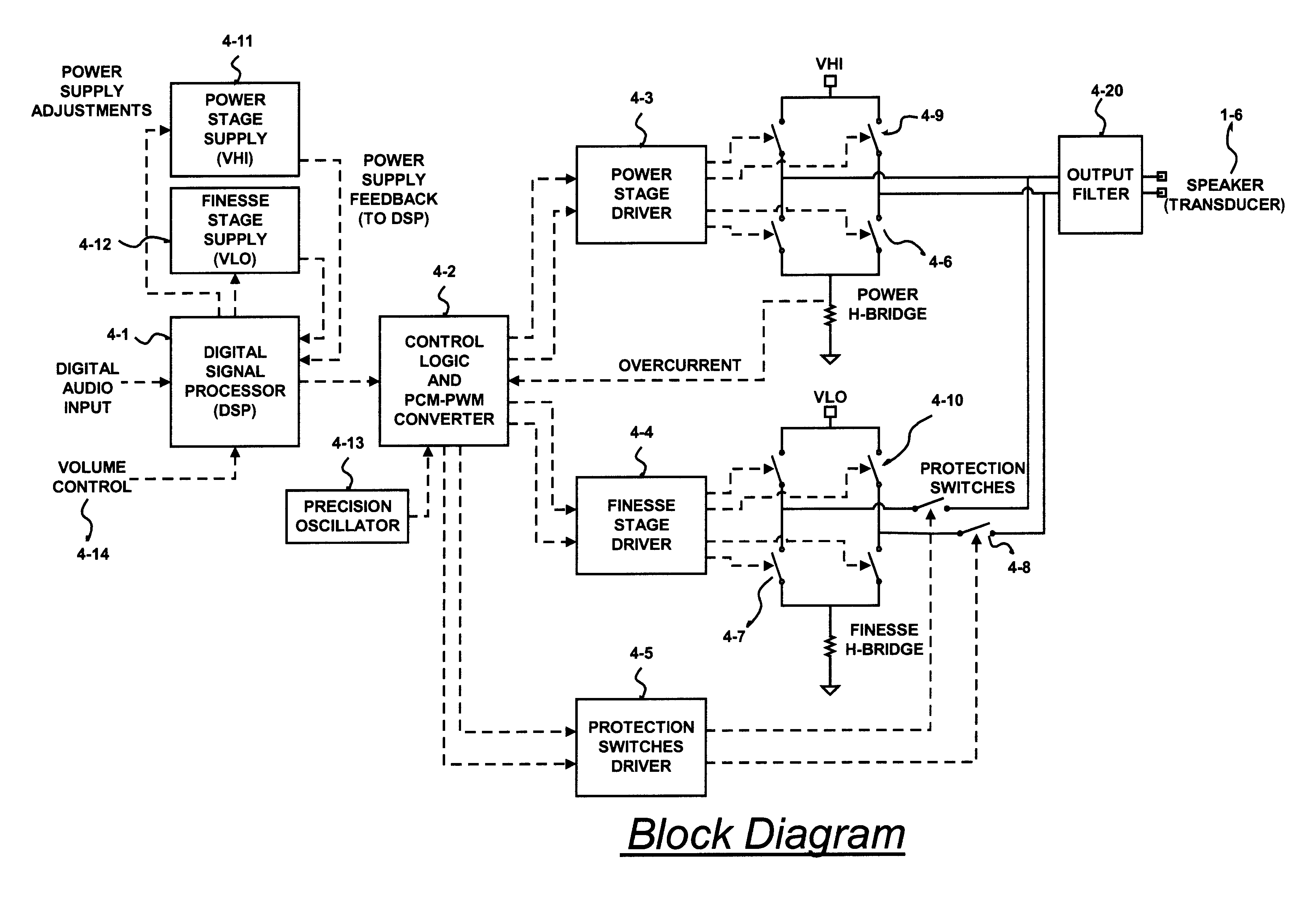
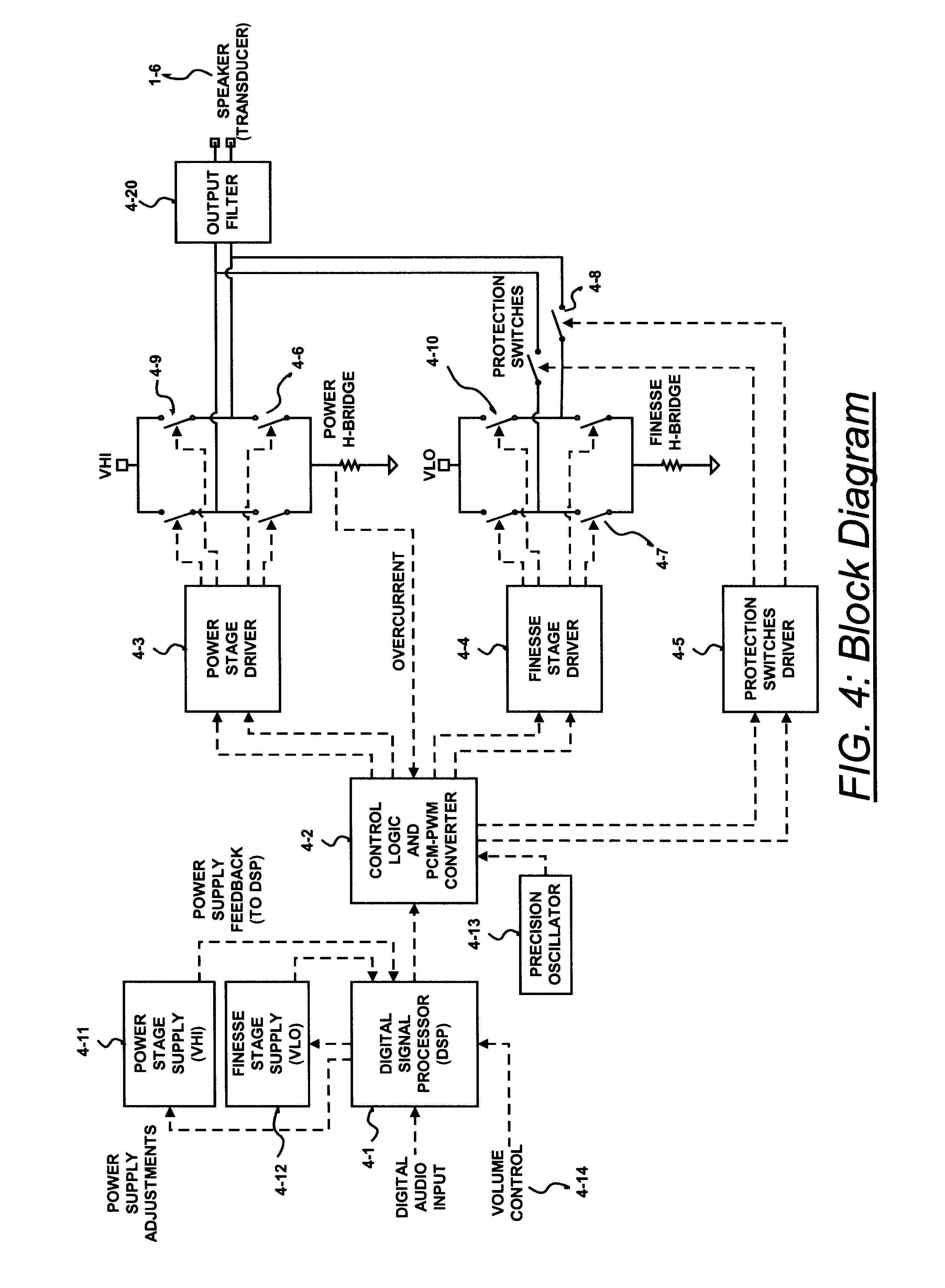
In view of the above background information, it is an object of the present invention to provide an efficient digital amplifier with increased dynamic range, improved linearity and lower total harmonic distortion through unique processing algorithms and the summation of one or mote additional pulse width modulated (PWM output stages.

Problems solved by technology

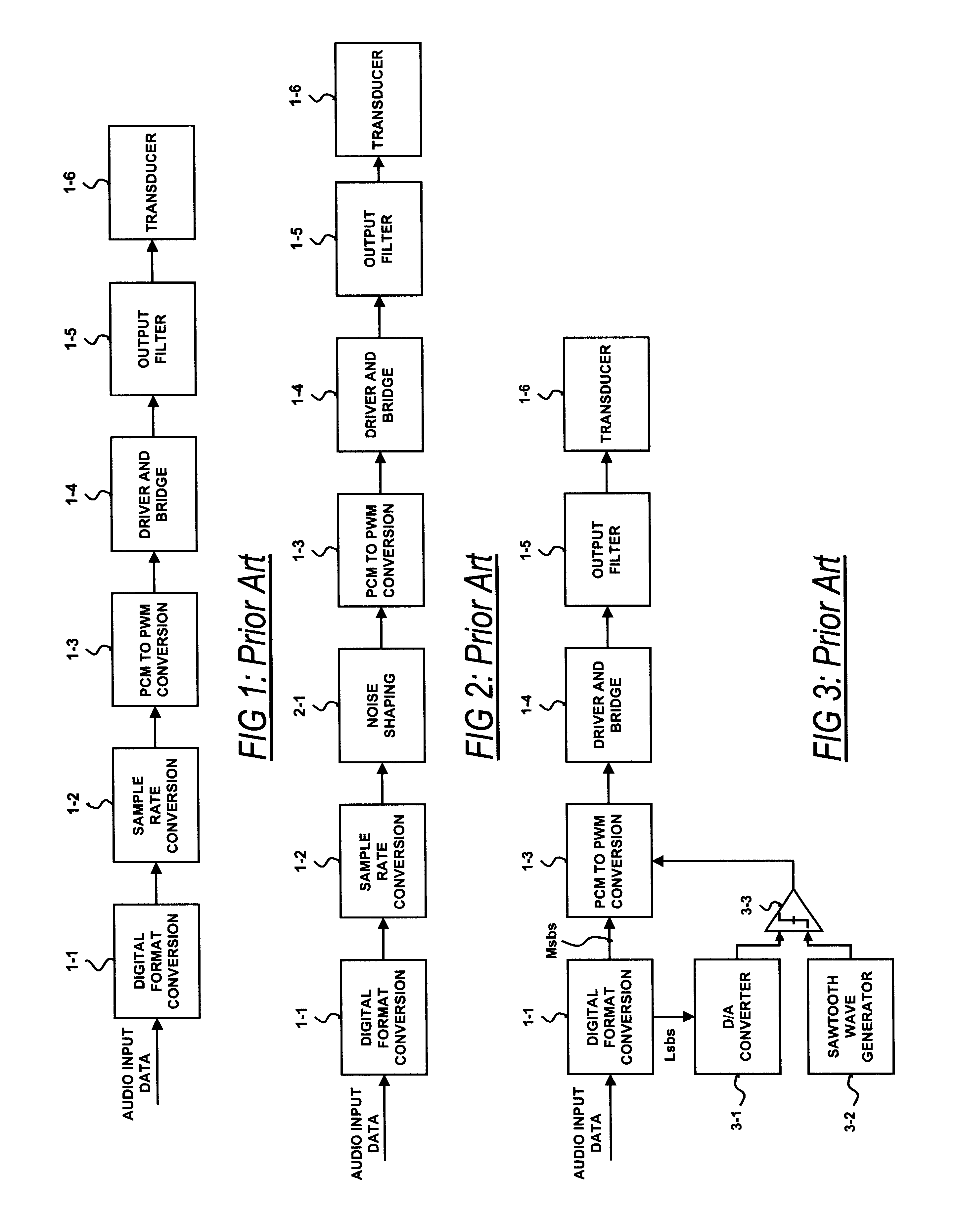
This unreasonable clock rate illustrates the limitations of this topology for audio CDs and other higher resolution digital formats currently on the market.
The noise-shaping filter reduces the required resolution of the input signal by placing the quantiser in a feedback loop with a digital filter, such that the filter quantisation error is subtracted from subsequent input samples.
However, system complexity and related risks are increased with the addition of a noise-shaping filter.
By placing the quantiser in a feedback loop, artifacts such as jitter, quantisation error and stability limit the practical performance.
Also, increasing the noise-shaping filter's order beyond three offers diminishing improvements in performance at reasonable oversampling rates.
A third prior art shown in FIG. 3 tries to overcome limits in resolution through an analog dithering scheme and is limited by the dithering circuitry.
However, quantisation errors of the D / A converter and linearity errors in the ramp generator limit the amount of resolution that may be obtained through the method.

Method used


Image

  • Digital amplifier with improved performance
  • Digital amplifier with improved performance
  • Digital amplifier with improved performance

Examples


example # 2

3.4. EXAMPLE #2

20 Bit, 96 KHz Input Audio

As a second example, consider a two-output stage amplifier for use with 20 bit, 96 Khz input audio. Each input audio sample could be split into 2 packets of 10-bit samples, with one packet for each output stage. The packets would consist of 8, 7-bit samples at an oversampling rate of 8*96 KHz=768 KHz. The period of each switching cycle (1 / 768 KHz) is broken up into two sections with the pulse from output stage #1 occupying the first half of the period and the pulse from output stage #2 occupying the second half of the period. In order to get 7 bits of resolution for each pulse a master clock of (2)*(2.sup.7)*768 KHz=196 MHz is used to clock the control logic which distributes the pulses. In order to reconstruct the input audio signal, the power supplies of the two output stages in this example, must be calibrated to have a ratio of 1024:1. As with the 16-bit example, the resolution of the above amplifier is increased by 1.5 bits (to 21.5 bits...


PUM


Abstract

A class D amplifier uses a summation of two or more PWM output stages to achieve an increased dynamic range and improved linearity for any given clock operating speed. The amplifier accepts a digital data stream as its input, such as from a compact disk, or other compatible media, at a data rate, Fa, that could be 44.1 kHz, 96 kHz, or any other rate appropriate for audio data. In the preferred embodiment, the input audio data resolution, N bits, would be split into two data samples, of J and K.Internal switching frequency, Fs, switches the PWM with an over sampling factor M, where Fs=M*Fa. The time resolution of the PWM is determined by a precision oscillator that operates at Fc=Fs*(max(J,K)-log2(M)+1).The J most significant bits would be routed to a power PWM stage operated at a DC voltage of VHI. The K least significant bits are routed to a finesse PWM stage operated at a DC voltage of VLO.The ratio of VLO to VHI will be appropriate for the ratio of K and J so the summation of the power PWM stage and the finesse PWM stage will provide the full range of N bits. This summation is accomplished with a low pass filter and time-division multiplexing of the two PWM stages.A micro controller (MCU) is used to apply a sample packet distribution algorithm to provide more resolution by reducing quantization noise in the audio band of interest. The MCU is also used to calibrate the VLO or VHI, or to calibrate the PWM timing of the two PWM stages to achieve appropriate performance.

Description

1. FIELD OF THE INVENTIONThis method refers to the field of electronic circuits and devices, and, mote particularly to a class D amplifier and related methods.2. BACKGROUND OF THE INVENTIONA class-D amplifier is a power D / A converter that is based on the duty-cycle D / A converter topology. Output devices of the amplifier are alternately switched at very high rates between two reference voltages creating a stream of output pulses. Each output pulse is low-pass filtered to remove the constant switching frequency, leaving an output voltage that is proportional to the duty-cycle of the pulse width and the difference of the two reference voltages. The exact switching times of the output devices are determined by the analog or digital audio input signal. With the use of fast and efficient devices in the output stage, high fidelity reproduction of input signals can be created with very little power loss in the amplifier thus allowing more effective delivery to the intended load of a speaker...

Claims


Application Information

Patent Timeline
Patent Type & Authority Patents(United States)
IPC IPC(8): H03F3/217H03F3/20
CPCH03F3/2173
Inventor GROVES, JR., WILLIAM HARRISAARON, ARTHUR ALAN
Owner GROVES JR WILLIAM HARRIS
Learn More