Brush and vacuum assembly and method of use

Inactive Publication Date: 2011-03-10
NSS ENTERPRISES
View PDF1 Cites 0 Cited by
  • Summary
  • Abstract
  • Description
  • Claims
  • Application Information

AI Technical Summary

Benefits of technology

[0006]The present invention is directed toward a brush and vacuum assembly and a method of its use. The assembly has a debris box selectively located within a debris box housing. At least one arm extends downwardly from a deck support

Problems solved by technology

Vacuuming requires additional equipment, time and labor.
However, known equipment that combines a floor scrubber with a vacuum apparatus has proven to be difficult to

Method used


Image

  • Brush and vacuum assembly and method of use
  • Brush and vacuum assembly and method of use
  • Brush and vacuum assembly and method of use

Examples


Example

[0016]It is to be understood that the invention may assume various alternative orientations and step sequences, except where expressly specified to the contrary. It is also to be understood that the specific devices and processes illustrated in the attached drawings, and described in the following specification are simply exemplary embodiments of the inventive concepts defined in the appended claims. Hence, specific dimensions, directions or other physical characteristics relating to the embodiments disclosed are not to be considered as limiting, unless the claims expressly state otherwise.

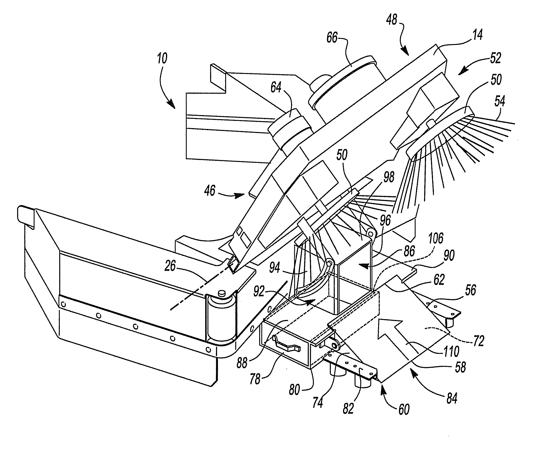
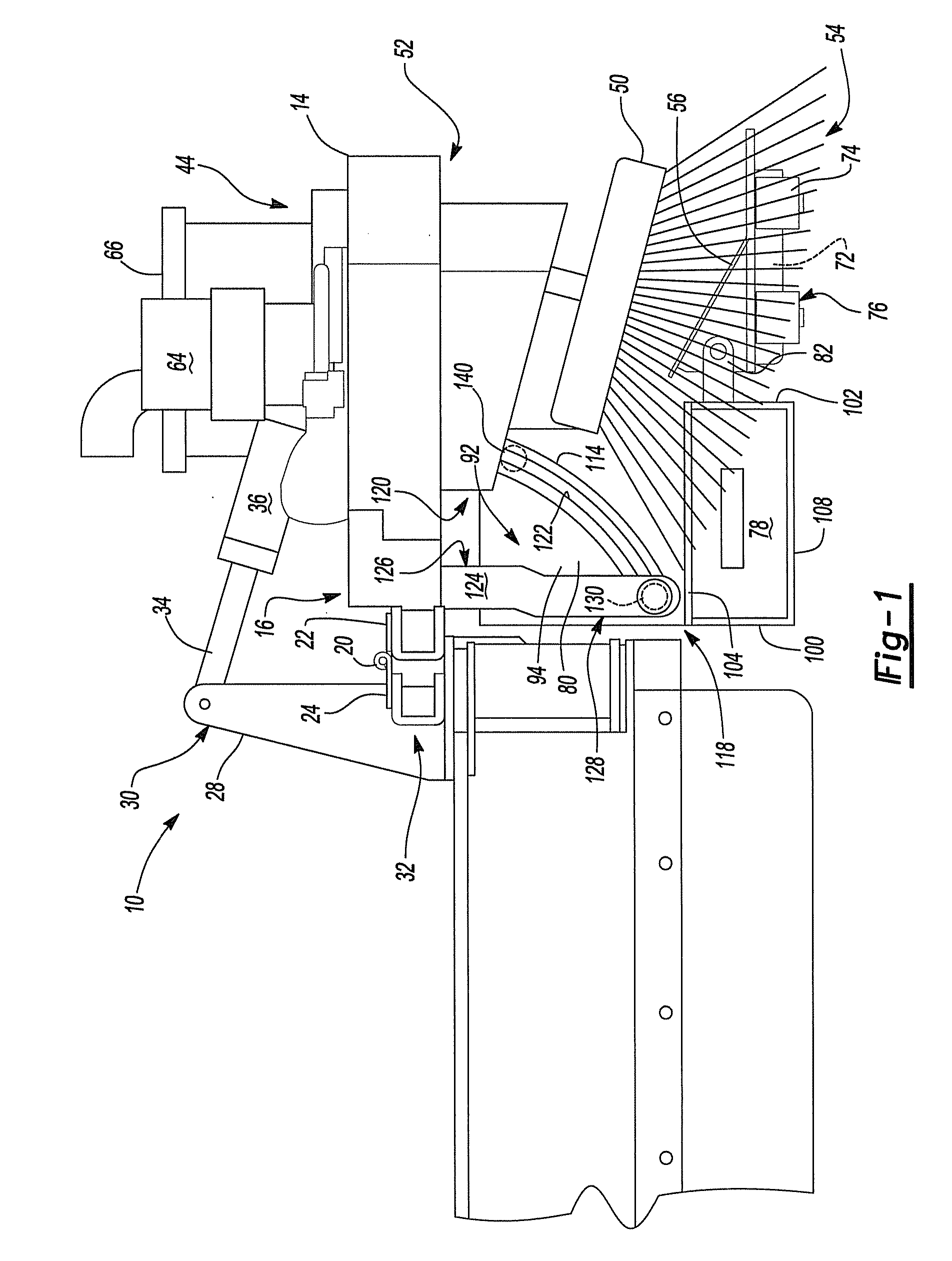
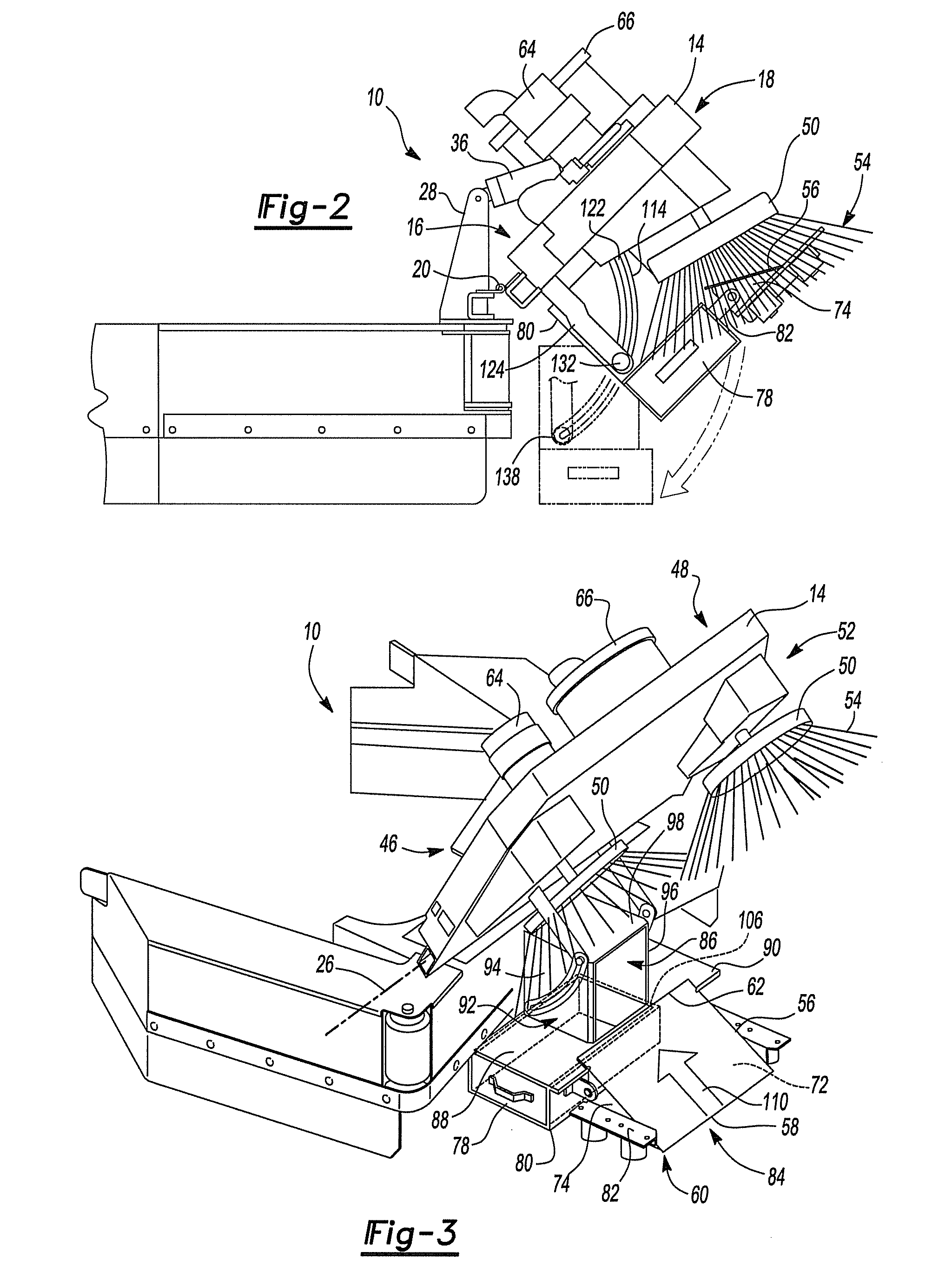
[0017]Turning now to FIG. 1, one embodiment of a brush and vacuum assembly 10 and part of a floor scrubber 12 is depicted. The assembly 10 comprises a deck 14. The deck 14 is connected to the floor scrubber 12. More particularly, a rear portion 16 of the deck 14 is connected to a front portion 18 of the floor scrubber 12. The connection may be made via one or more hinges 20. The hinges 20 are also...


PUM


Abstract

A brush and vacuum assembly and its method of use are provided. The assembly has a debris box selectively located within a debris box housing. At least one arm extends from a deck that supports at least one brush motor. At least one pin extends through the at least one arm for selective engagement with the debris box housing. The layout permits the debris box to be accessed from a side of the machine.

Description

RELATED APPLICATIONS[0001]This application claims the benefit of U.S. Patent Application Ser. No. 61 / 276,221 filed on Sep. 9, 2009, which is incorporated by reference in its entirety.FIELD OF THE INVENTION[0002]The present invention relates to a brush and vacuum assembly and its method of use. More particularly, the invention relates to a brush and vacuum assembly and method of use with floor cleaning equipment, such as a floor scrubber.BACKGROUND OF THE INVENTION[0003]The present invention is an improvement over known floor cleaning equipment, such as floor scrubbers. Most floor scrubbers have a water supply, a cleaning solution and outlets that apply the water and / or cleaning solution onto a floor. A set of rotary brushes works the cleaning solution into the floor to lift dirt and debris from the floor and scrub the floor clean. A squeegee and water suction device may be located at the rear of the machine to collect excess water and cleaning solution from the floor.[0004]Those ski...

Claims


Application Information

Patent Timeline
IPC IPC(8): A47L9/00
CPCA47L11/4025A47L11/302
Inventor RUPP, MARK N.KATTI, ANILKUMAR P.KUMAR DASH, CHOUDHURI SRI CHINMAYA
Owner NSS ENTERPRISES
Why Eureka
Try Eureka