Automated chest compression device

a chest compression and automatic technology, applied in the field of cpr, can solve the problems of inconvenient belt installation in either device, cpr-based compression devices, and ineffective clinical use, and achieve the effects of convenient removal and replacement of belts, convenient belt removal, and convenient belt removal

Active Publication Date: 2020-05-05
ZOLL CIRCULATION
View PDF261 Cites 1 Cited by
  • Summary
  • Abstract
  • Description
  • Claims
  • Application Information

AI Technical Summary

Benefits of technology

[0007]The devices and methods described below provide for a belt-driven chest compression device in which the compression belt is readily replaceable. The chest compression device includes a platform which houses drive components, and a compression belt which is connected to the drive components through releasably attachable couplings near the upper surface of the device. Removal and replacement of the belt may be accomplished while a patient is disposed on the housing. This arrangement helps avoid twisting of the belt and facilitates removal and replacement of the belt. Installation of the belt is simpler than our prior AUTOPULSE® device, and is tensioned upon installation by the user. To ensure that compression cycles start from an optimum low level of tightness, without slack, the control system of the device may control the device to loosen the belt upon start-up and thereafter draw the belt to the slack take-up position, or to tighten the belt upon start-up while monitoring an indicator of tightness (motor current, load on a load cell, strain on the belt), and conditionally tighten the belt to a slack take-up position (if the belt is loose initially) or reverse and loosen the belt and then tighten the belt while monitoring an indicator of tightness, to tighten the belt to a slack take-up position (if the initial tightness exceeds the desired tightness of a slack take-up position).

Problems solved by technology

Other belt-based CPR compressions devices have been proposed, but not implemented in clinical use.
Belt installation is not convenient in either device.
No other automated CPR chest compression device is capable of holding compressions at a high threshold of compression.
This is not possible if the radiopaque metal components of the chest compression device (the motor and drive train) are located directly under the load distributing portion of the compression belt, which overlies the patient's chest and heart when properly installed, so that the radiopaque component are also located under the heart.

Method used


Image

  • Automated chest compression device
  • Automated chest compression device
  • Automated chest compression device

Examples


Embodiment Construction

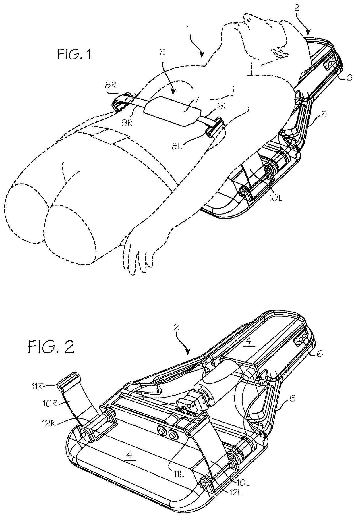
[0018]FIG. 1 shows the chest compression device fitted on a patient 1. The chest compression device 2 applies compressions with the compression belt 3. The chest compression device 2 includes a belt drive platform 4 sized for placement under the thorax of the patient, upon which the patient rests during use and which provides a housing 5 for the drive train and control system for the device. The control system, embedded anywhere in the device, can include a processor and may be operable to control tightening operation of the belt and to provide output on a user interface disposed on the housing. Operation of the device can be initiated and adjusted by a user through a control panel 6 and a display operated by the control system to provide feedback regarding the status of the device to the user.

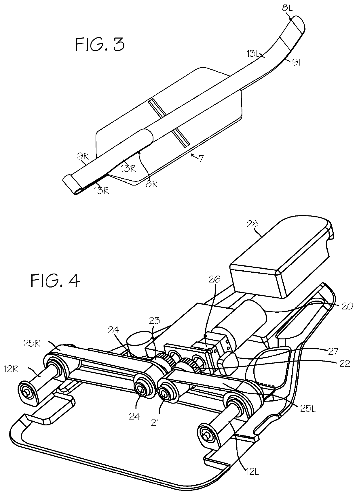
[0019]The belt includes a wide load-distribution section 7 at the mid-portion of the belt and left and right belt ends 8R and 8L (shown in the illustration as narrow pull straps 9R and 9L), wh...


PUM


Abstract

A device for compressing the chest of a cardiac arrest victim.

Description

FIELD OF THE INVENTIONS[0001]The inventions described below relate to the field of CPR.BACKGROUND OF THE INVENTIONS[0002]Cardiopulmonary resuscitation (CPR) is a well-known and valuable method of first aid used to resuscitate people who have suffered from cardiac arrest. CPR requires repetitive chest compressions to squeeze the heart and the thoracic cavity to pump blood through the body. In efforts to provide better blood flow and increase the effectiveness of bystander resuscitation efforts, various mechanical devices have been proposed for performing CPR. In one variation of such devices, a belt is placed around the patient's chest and the belt is used to effect chest compressions, for example our commercial device, sold under the trademark AUTOPULSE®. Our own patents, Mollenauer, et al., Resuscitation Device Having A Motor Driven Belt To Constrict / Compress The Chest, U.S. Pat. No. 6,142,962 (Nov. 7, 2000); Sherman, et al., CPR Assist Device with Pressure Bladder Feedback, U.S. P...

Claims


Application Information

Patent Timeline
Patent Type & Authority Patents(United States)
IPC IPC(8): A61H31/00A61H11/00
CPCA61H31/006A61H2201/1445A61H2201/501A61H2201/5064A61H2201/5061A61H2011/005A61H2201/1623A61H2201/1604A61H2201/018A61H31/005A61H2201/5043
Inventor JOSHI, NIKHIL S.HARRIS, MELANIE L.REYNOLDS, BYRON J.
Owner ZOLL CIRCULATION
Why Eureka
Try Eureka