Terminal structure for plate-shaped member having conducting function, and plate-shaped member having conducting function

a technology of conducting function and terminal structure, which is applied in the direction of cable junction, cable fitting, electric cable installation, etc., can solve the problems of increasing the thickness of the glass panel considerably, not considering the thickness of the smallest part, etc., to achieve easy positioning, high connection safety, and increase the thickness dimension

Inactive Publication Date: 2011-03-10
NIPPON SHEET GLASS CO LTD
View PDF2 Cites 22 Cited by
  • Summary
  • Abstract
  • Description
  • Claims
  • Application Information

AI Technical Summary

Benefits of technology

[0017]An object of the present invention is to provide a terminal structure for a conducting-function-imparted plate-shaped member in which an increase in the thickness dimension of a plate-shaped member provided so as to be moveable in the plane direction of a main surface, such as an automotive window pane, is kept to a minimum, which can be positioned with ease, which has a predetermined level of strength, and which has high connection safety; and to provide a conductive-function-imparted plate-shaped member that is equipped with the terminal structure.
[0018]Another object of the present invention is to provide a terminal structure for a conducting-function-imparted plate-shaped member, and to provide a conducting-function-imparted plate-shaped member for which acid resistance and weather resistance can be achieved.

Problems solved by technology

However, in the conventional technique described in Patent Document 1 or 2, no consideration is given to minimizing the thickness of the glass panel that includes the electrode terminal and the conductive film formed on the main surface, and problems are presented when the glass panel provided with the terminal structure is used, for example, as an automotive window pane.
This structure presents a problem in that when it is applied to an automotive window pane, the thickness increases considerably in comparison with the thickness of the glass panel, complicating the assembly process and compromising the reliability and safety of connection.
A problem is presented in that the glass panel cannot be inserted through the entrance when there is a protrusion that extends in the thickness direction of the glass panel.
Another problem is that even when the glass panel can be inserted through the entrance, careful operations are required to prevent the glass panel from colliding with the periphery of the entrance, reducing the operating efficiency or changing the joining state by the collision and compromising the safety of the connection.
The conventional technique disclosed in Patent Document 3 can minimize the increase in the thickness dimension of the glass panel, but the terminal structure is still difficult to position in relation to the glass panel, and the technique is not necessarily satisfactory in practical terms.

Method used


Image

  • Terminal structure for plate-shaped member having conducting function, and plate-shaped member having conducting function
  • Terminal structure for plate-shaped member having conducting function, and plate-shaped member having conducting function
  • Terminal structure for plate-shaped member having conducting function, and plate-shaped member having conducting function

Examples


embodiment 1

[0092]FIG. 6 is a diagram showing a state in which a terminal structure 10 for a conducting-function-imparted plate-shaped member is used on a window pane 11 for an automotive vehicle door. In FIG. 6, a conductive film 12 is formed on an end part and a main surface along a top edge and left and right edges of the window pane 11. The conductive film functions as, e.g., a conductor of an obstruction detection sensor. The conductive film 12 extends to a part of a lower edge of the window pane 11, and the terminal structure 10 is attached on a lower end of the window pane 11 to which the conductive film 12 is provided. The conductive film 12 may instead be provided on an end face, as shown in FIG. 8. A linking part 7 is a portion for linking the window pane to a window regulator.

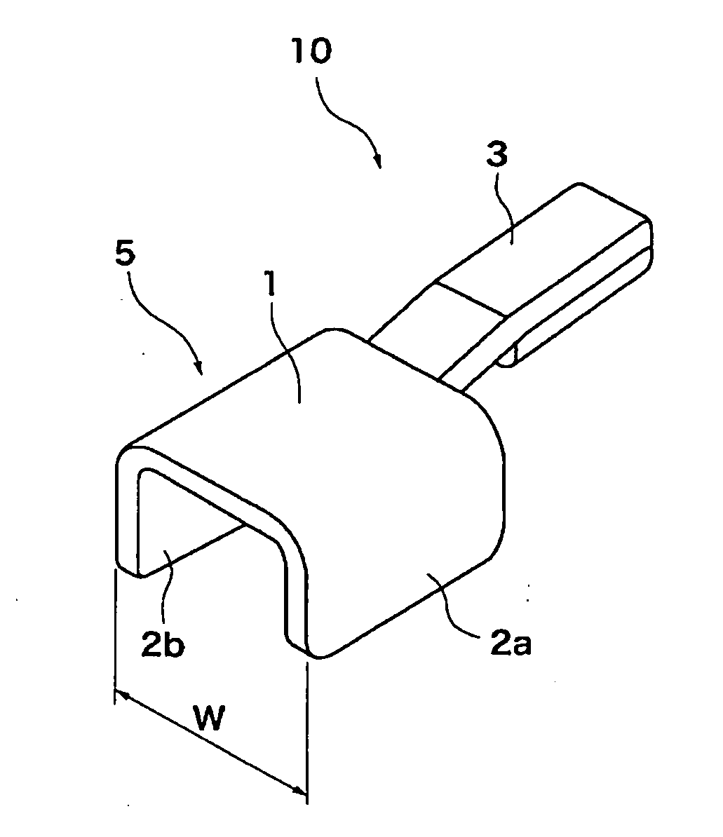
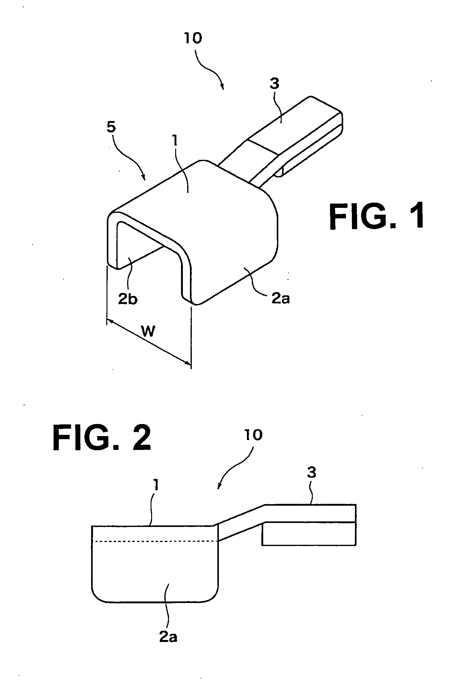
[0093]FIG. 7 is an expanded perspective view showing the vicinity of the terminal structure 10 shown in FIG. 6. The terminal structure 10 having a joint unit 5 that has a U-shape in cross section is used in the ...

embodiment 2

[0101]FIG. 8 is a diagram showing Embodiment 2. The embodiment shown in FIG. 8 differs from the first embodiment shown in FIG. 7 in that an conductive film 12 is provided to an end face 13 of the window pane 11. In FIG. 8, the terminal structure 10 abuts the end part of the window pane 11, and the abutting portion 1 and the conductive film 12 are joined by solder (not shown).

[0102]In the present embodiment, the increase in the thickness dimension of the window pane 11 as a result of the terminal structure 10 having been attached is equal to the increase in dimension in Embodiment 1 less the solder film thickness.

[0103]In other words, the increase in dimension is as follows:

(3.1 to 4.1)−0.5→2.6 to 3.6 (mm)

[0104]Also, the thickness dimension of the entirety of the window pane 11 provided with the terminal structure 10 is as follows:

(2.6 to 3.6)+3.0→5.6 to 6.6 (mm)

embodiment 3

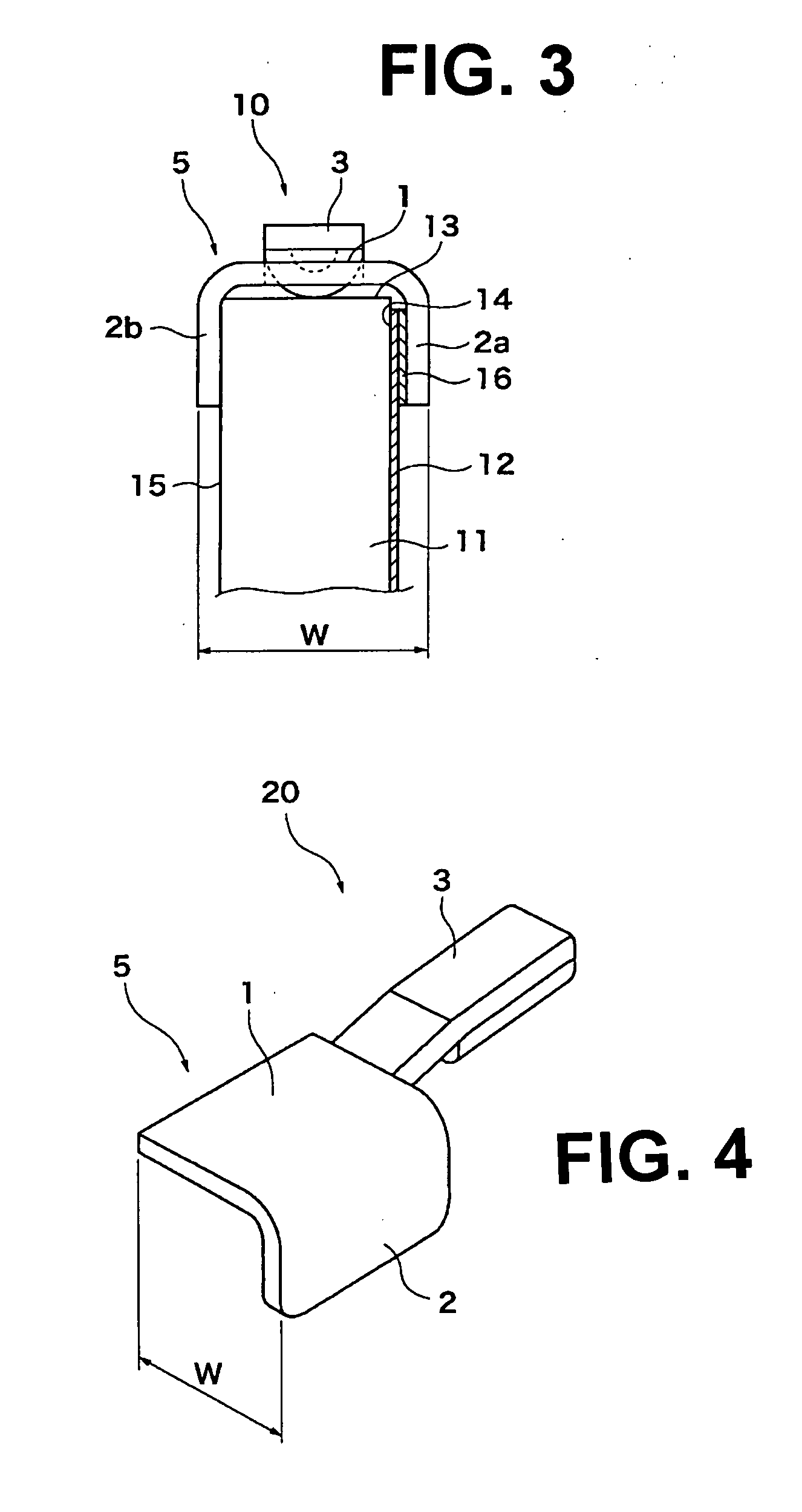
[0105]FIG. 9 is a diagram showing Embodiment 3. The embodiment shown in FIG. 9 differs from Embodiment 1 shown in FIG. 7 in that a terminal structure 20 having a joint unit that is L-shaped in cross section is provided as the terminal structure. In FIG. 9, the terminal structure 20 is positioned on the window pane 11 using a joint unit 5 of the terminal structure 20, the joint unit being L-shaped in cross section; and a protruding portion 2 and the conductive film 12 are joined by solder (not shown).

[0106]In the present embodiment, the increase in the thickness dimension of the window pane 11 as a result of the terminal structure 20 having been attached is the sum of the thickness of the protruding portion 2 forming the joint unit 5 having an L-shape in cross section, the thickness of a solder film (not shown) formed on a surface of the protruding portion 2, and the thickness of an insulating resin coating (not shown) covering the entirety of the terminal structure 20. Assuming that...


PUM


Abstract

Disclosed is a terminal structure, which suppresses the increase in the thickness size of a plate-shaped member disposed movably in the direction of main surfaces (14 and 15) so that it can be easily positioned and connected, and which is used in an automotive window glass pane (11) having a predetermined strength, an acid resistance and a weather resistance. The terminal structure (10) comprises a joint unit (5) and a terminal unit (3). The joint unit (5) includes an abutting portion (1) for abutting against the side faces of the end portion of the window glass pane, and protruding portions (2a and 2b) extending from the abutting portion (1) along the main surfaces (14 and 15) of the window glass pane. The terminal unit is disposed to lie within a width (W) of the joint unit in the thickness direction of the window glass pane, and at least a portion of the joint unit is jointed to a conductive film (12) so that the conductive film and the terminal unit are electrically connected.

Description

TECHNICAL FIELD[0001]The present invention relates generally to a terminal structure for a conducting-function-imparted plate-shaped member as well as to the conductive plate-shaped member. More particularly, it relates to a terminal structure for a conductive-film-equipped automotive window glass pane that is moved by a window regulator in a direction of a main surface of the glass pane and to the window glass pane equipped with the terminal structure.BACKGROUND ART[0002]Already known are automotive window panes having formed thereon, for example, an conductive film for generating heat in order to melt frost, snow, ice, or a similar material attached to a surface of a glass panel; an conductive film having an antenna function; an conductive film as a sensor for detecting cracks in a glass panel to prevent crime; or the like. Conductive films of such description are primarily formed on a windshield (front window pane) or rear glass (rear window pane), but in recent years are occasio...

Claims


Application Information

Patent Timeline
Patent Type & Authority Applications(United States)
IPC IPC(8): H02G3/06
CPCH01R4/023H01R4/187H01R4/182
Inventor MATSUSHITA, YOSHIMITSUKATAKURA, SEIJISUEDA, MASAMI
Owner NIPPON SHEET GLASS CO LTD
Why Eureka
Try Eureka