
Oceanic communications system

a communication system and ocean technology, applied in the field of ocean-based communications, can solve the problems that ocean-based communications systems, such as submarine fiber optic cables, do not offer data paths to the surface of the ocean, and achieve the effect of high-bandwidth communications

Inactive Publication Date: 2011-03-10
PLENTL BRETT A
View PDF8 Cites 18 Cited by
  • Summary
  • Abstract
  • Description
  • Claims
  • Application Information

AI Technical Summary

Benefits of technology

The present invention is a system of buoys, connected by vertical cables to submarine fiber optic communications cable on the ocean floor or in cases where no submarine fiber optic cable is present, the buoys will use satellite communication. The buoys are aligned on the surface of the ocean, underneath heavily traveled oceanic air routes to provide platforms for radios. The satellite or cable connection to the buoys enable high bandwidth communications backhaul from the buoy to the interne or public switched telephone network. The high bandwidth buoys provide a platform to put different radio systems, enabling a substantially uninterrupted radio connection to high altitude aircraft as they transit oceanic airspace.

Problems solved by technology

Current ocean-based communications systems, such as submarine fiber optic cable, do not offer data paths to the surface of the ocean, except at the cable landing stations.

Method used


Image

  • Oceanic communications system
  • Oceanic communications system
  • Oceanic communications system

Examples


Embodiment Construction

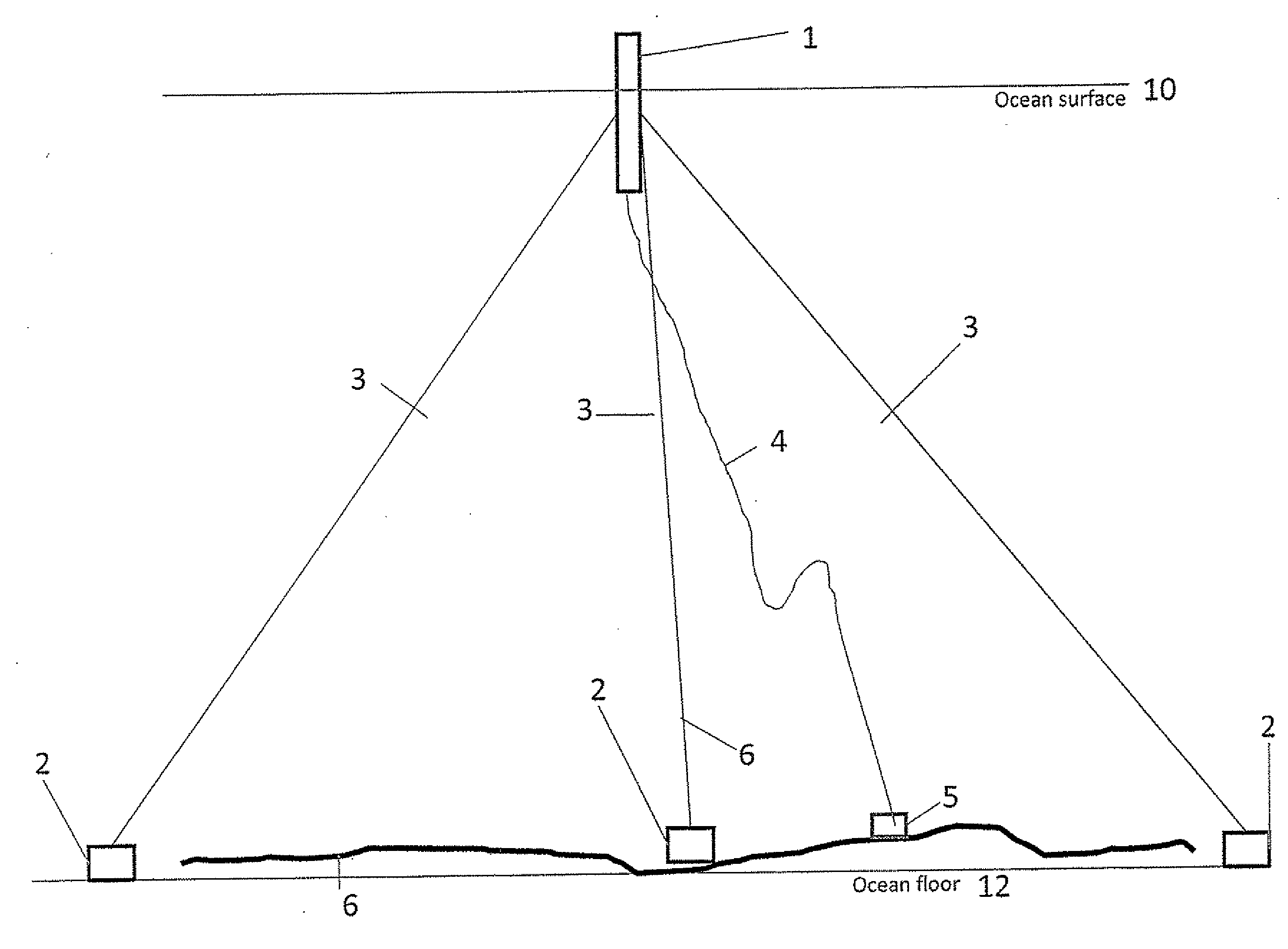
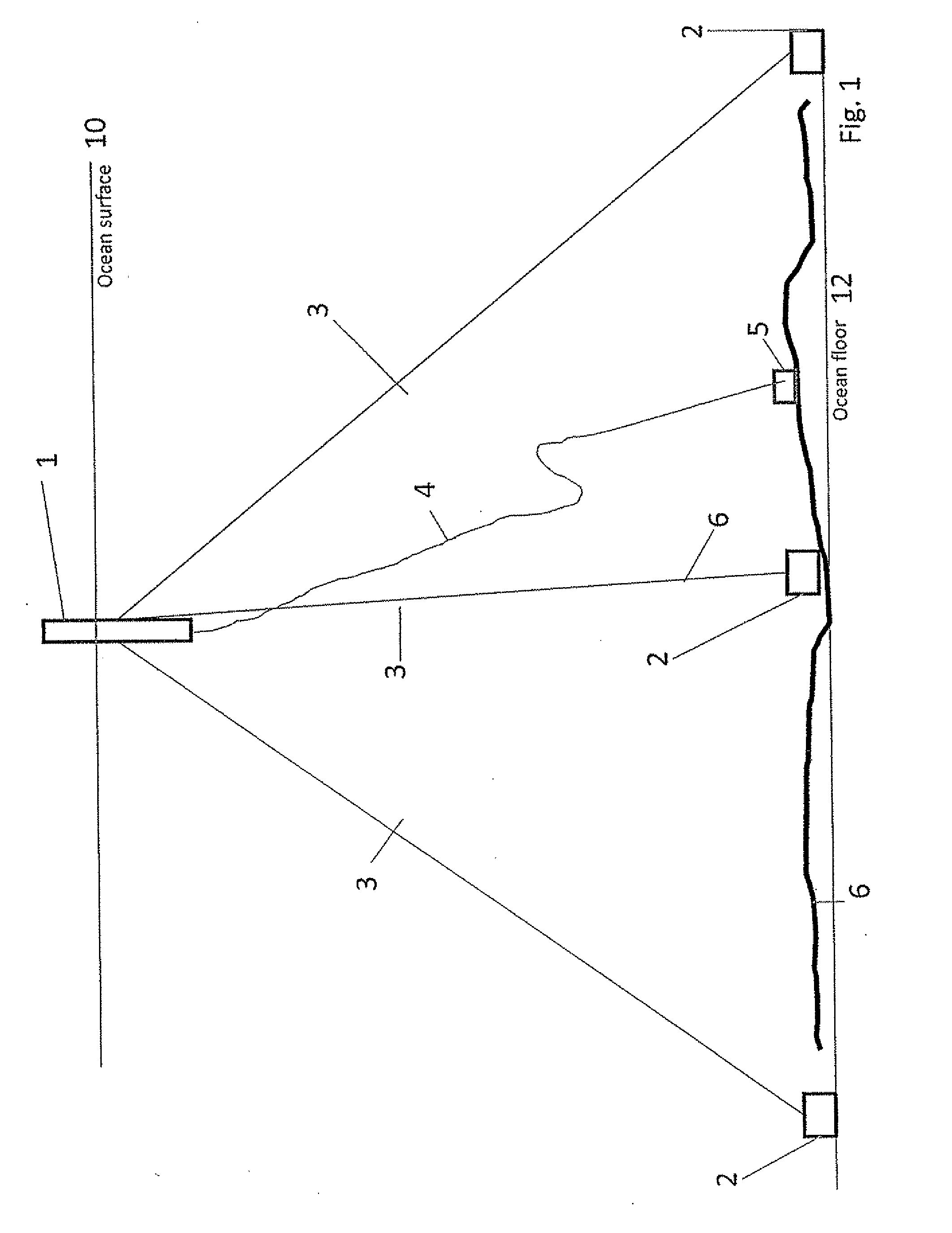
Referring now to the invention in more detail, in FIG. 1 and FIG. 2 there is shown a large buoy or structure 1 floating on the surface of the ocean 10 and attached to the ocean floor 12 by a combination of anchors 3 and mooring lines. 2. The buoy or structure 1 is also attached to an undersea junction box or branching unit 5 by a dynamic riser 4. The undersea junction box 5 is also attached to an undersea fiber optic cable system 6. When no fiber optic submarine cable is available, satellite communications will be used.

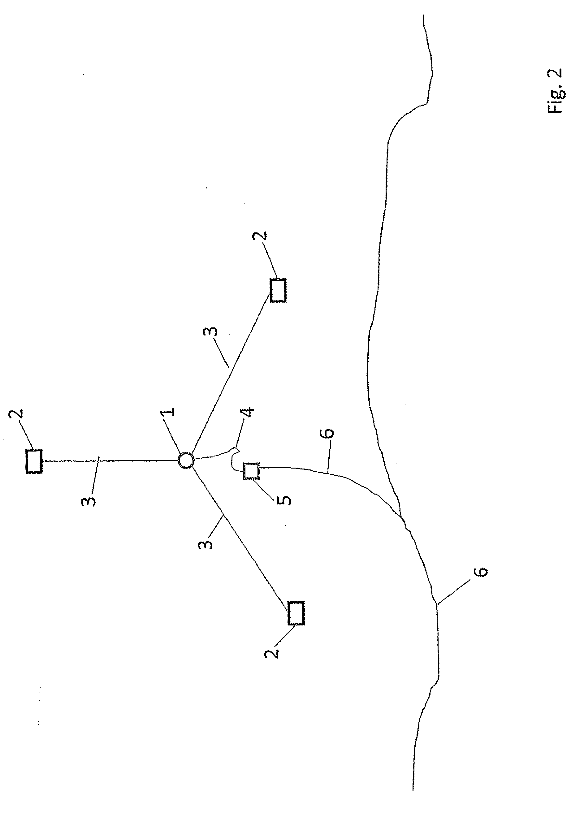
FIG. 3 depicts a Top System View of several large buoys or structures 1 moored in position by anchors 3 and mooring lines 2, and attached by dynamic risers 4 to the submarine junction box or branching unit 5 and to a submarine fiber optic cable system 6. When no fiber optic submarine cable is available, satellite communications will be used. The several large buoys or structures 1 are optimally positioned on the surface of the ocean under heavily traveled air routes.

I...


PUM


Abstract

A system of buoys is connected by vertical cables to submarine fiber optic communications cable on the ocean floor or in cases where no submarine fiber optic cable is present, the buoys will use satellite communication. The buoys are aligned on the surface of the ocean, underneath heavily traveled oceanic air routes to provide platforms for radios. The satellite or cable connection to the buoys enables high bandwidth communications backhaul from the buoy to the internet or public switched telephone network. The high bandwidth buoys provide a platform to put different radio systems, enabling a substantially uninterrupted radio connection to high altitude aircraft as they transit oceanic airspace.

Description

BACKGROUND OF THE INVENTIONThe present invention is in the technical field of communications. More particularly, the present invention is in the technical field of ocean-based communications.Current ocean-based communications systems, such as submarine fiber optic cable, do not offer data paths to the surface of the ocean, except at the cable landing stations. Aircraft or ships transiting the ocean are dependent on satellite-based communications systems, even though the routes they fly or sail often approximate the same paths where submarine fiber optic cable is laid on the ocean floor.BRIEF SUMMARY OF THE INVENTIONThe present invention is a system of buoys, connected by vertical cables to submarine fiber optic communications cable on the ocean floor or in cases where no submarine fiber optic cable is present, the buoys will use satellite communication. The buoys are aligned on the surface of the ocean, underneath heavily traveled oceanic air routes to provide platforms for radios. ...

Claims


Application Information

Patent Timeline
IPC IPC(8): H04B10/00
CPCB63B22/16H04B10/272B63B51/00
Inventor PLENTL, BRETT A.
Owner PLENTL BRETT A
Learn More