
Process for manufacture and assembly of battery modules and sections

Inactive Publication Date: 2011-03-10
GM GLOBAL TECH OPERATIONS LLC
View PDF6 Cites 5 Cited by
  • Summary
  • Abstract
  • Description
  • Claims
  • Application Information

AI Technical Summary

Benefits of technology

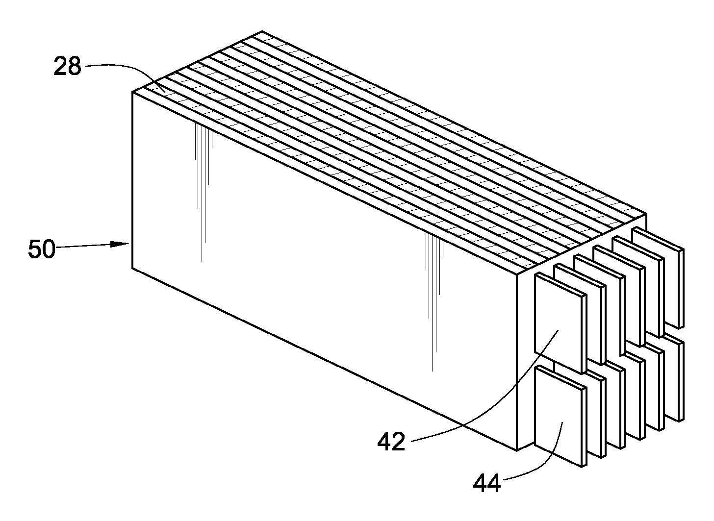
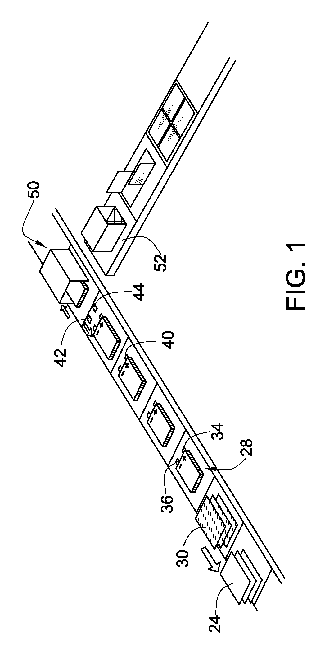
[0010]The present invention reduces the difficulties and disadvantages of the prior art by providing an improved rechargeable battery and assembly thereof the method including the steps of providing at least one pair of electrically biased sheets to form a plurality of positive and negative electrodes; forming a cell element from three positive electrodes spaced from three negative electrodes in an overlying orientation with a positive and negative lead terminal extending respectively therefrom; separating each of said positive and negative electrodes with a polymer layer; electrically aligning said positive lead terminals and negative lead terminals; applying a heat protectant to the positive lead terminals and the negative lead terminals; shaping said positive and negative lead terminals for connecting to a pair of electrode current collectors, one of said current collectors being associated with s

Problems solved by technology

Despite advances in the field of electrochemical storage, the conventional process for manufacturing such batteries remains complex and expensive, comprising a multiplicity of independently executed steps.
As it is evident from the above steps, lithium ion battery manufacturing involves many labor intensive handling operations, each of which incurs substantial investments of time and capital.
The conventional manufacturing process described above represents a labor-intensive “pick and place” operation that retards the manufacturing process and thereby accelerates the costs associated therewith.
Individual handling of cells is not only tedious; it also fosters improper alignment of the components of the cell assembly, leading to improper cell performance and limited yield of the number of batteries produced per production run.

Method used


Image

  • Process for manufacture and assembly of battery modules and sections
  • Process for manufacture and assembly of battery modules and sections
  • Process for manufacture and assembly of battery modules and sections

Examples


Embodiment Construction

[0016]The present invention is directed to a lithium-ion cell assembly and method of manufacture thereof. Generally, the present invention relates to a battery pack, a lithium ion battery, for example, and a method of manufacturing such battery pack.

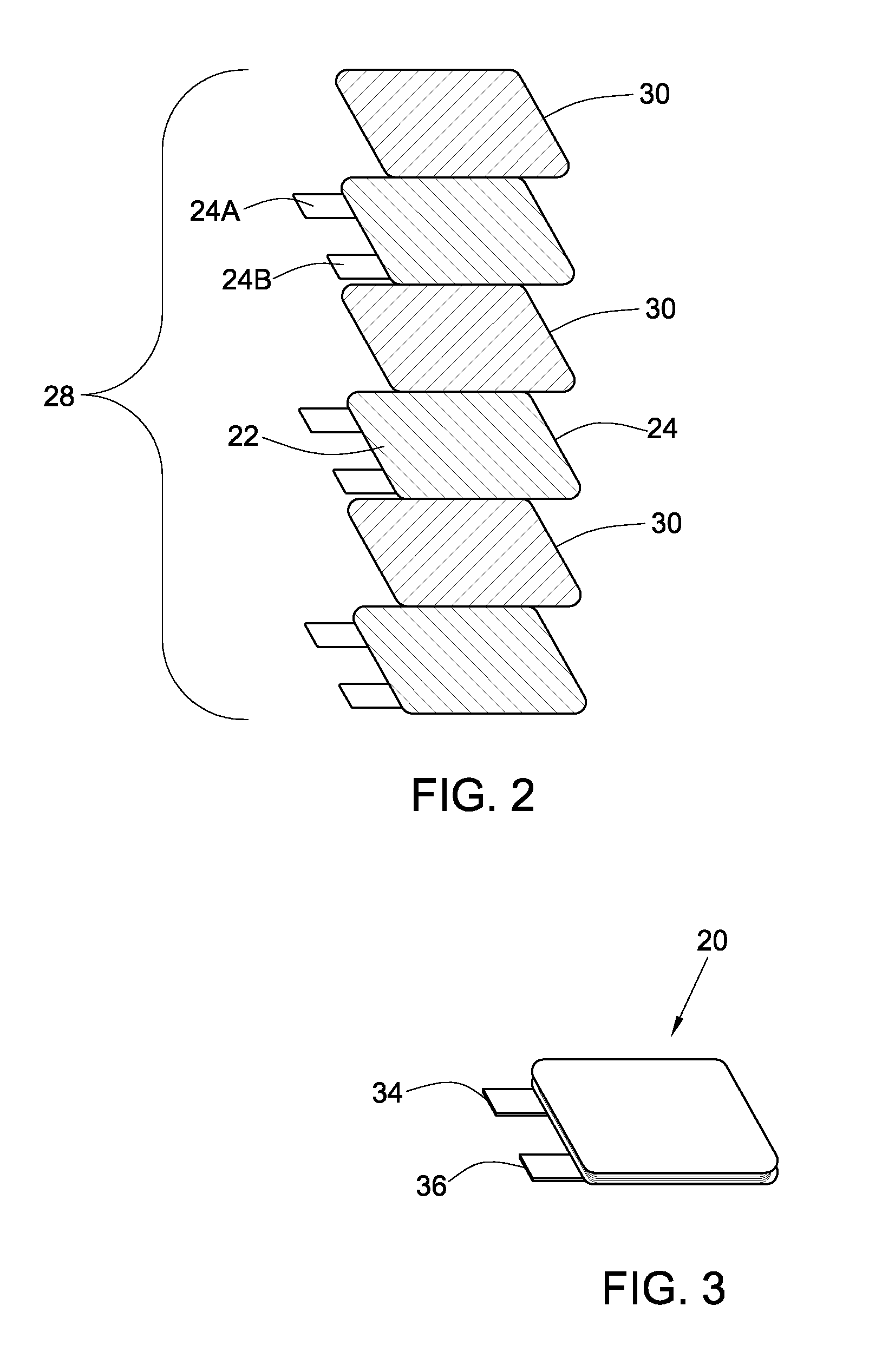
[0017]Hereinbelow, a preferred embodiment of the present invention will be described with reference to the drawings according to the assembling order. In FIGS. 1-5, reference numeral 20 generally references to a cell for a battery made of lithium ion, for example. The cell 20 includes a cell element 24 and is generally covered with a hard laminate material 22 designed to protect the cell 20.

[0018]The cell element 24 includes a positive electrode 24a, a negative electrode 24b, and is adapted for receiving a polymer and / or a separator 30 disposed between the positive and negative electrodes 24a,24b. The electrodes 24a,24b are generally positioned in an overlying orientation in relation to each other, wherein the positive electrode 24a and ...


PUM

PropertyMeasurementUnit
Bending strengthaaaaaaaaaa

Abstract

The present invention provides an improved rechargeable battery and method of assembling the same, including the steps of providing at least one pair of electrically biased sheets to form a plurality of positive and negative electrodes; forming a cell element from three positive electrodes spaced from three negative electrodes in an overlying orientation with a positive and negative lead terminal extending respectively therefrom; separating each of the positive and negative electrodes with a polymer layer; electrically aligning said positive lead terminals and negative lead terminals; applying a heat protectant to the positive and negative lead terminals; shaping the positive and negative lead terminals for connecting to a pair of electrode current collectors, wherein one of the collectors is associated with the positive lead terminal and the other with the negative lead terminal; and providing a frame for receiving cell elements, such that the rechargeable battery provides the desired electrical characteristics.

Description

FIELD OF THE INVENTION[0001]The present invention is directed to an advanced method of manufacturing and assembling battery modules and sections, namely batteries based on Lithium-Ion electrochemical cells and related chemical analogues. In particular, the present invention is directed to a method of assembling components of lithium-ion polymer battery modules and sections.BACKGROUND OF THE INVENTION[0002]Lithium ion batteries represent the state-of-the-art in rechargeable battery technology. A rechargeable lithium ion battery contains an electrolyte through which lithium atoms from a source electrode move between electrodes during charge / discharge cycles. Each individual lithium-ion cell is comprised of a conductive polymer membrane in a lithium salt matrix sandwiched between an anode and a cathode. Lithium-ion batteries are often packaged such that multiple cells are connected either in series or parallel depending on the application, which are further arranged into modules.[0003]...

Claims


Application Information

Patent Timeline
IPC IPC(8): H01M4/58H01M10/04
CPCH01M2/22H01M10/052H01M10/0565H01M10/0585Y10T29/49115H01M10/5046Y02E60/122Y02T10/7011H01M10/5004H01M10/613H01M10/6551H01M50/528Y02E60/10Y02P70/50Y02T10/70
Inventor MEEHAN, PATRICK J.SCHEUERMAN, ROBERT J.ROURKE, RICK F.
Owner GM GLOBAL TECH OPERATIONS LLC
Learn More