Doctor blade chamber

a blade chamber and blade technology, applied in the direction of printing press parts, printing, printing presses, etc., can solve the problems of insufficient ink waste, optimal methods, time-consuming and/or tedious, etc., and achieve the effect of fast change of ink and/or replacemen

Active Publication Date: 2011-03-17
TRESU
View PDF5 Cites 8 Cited by
  • Summary
  • Abstract
  • Description
  • Claims
  • Application Information

AI Technical Summary

Benefits of technology

[0009]It is thus the object of the invention to indicate a method for mounting and dismounting a doctor blade chamber and to indicate a doc

Problems solved by technology

By this solution, however, there is still a minor waste of ink, and at the same time it is necessary to adapt the printing unit such that there is less space for inserting this gate by sliding, which is to be inserted from the end of the roller and thus requiring free space in longitudin

Method used


Image

  • Doctor blade chamber
  • Doctor blade chamber
  • Doctor blade chamber

Examples


Embodiment Construction

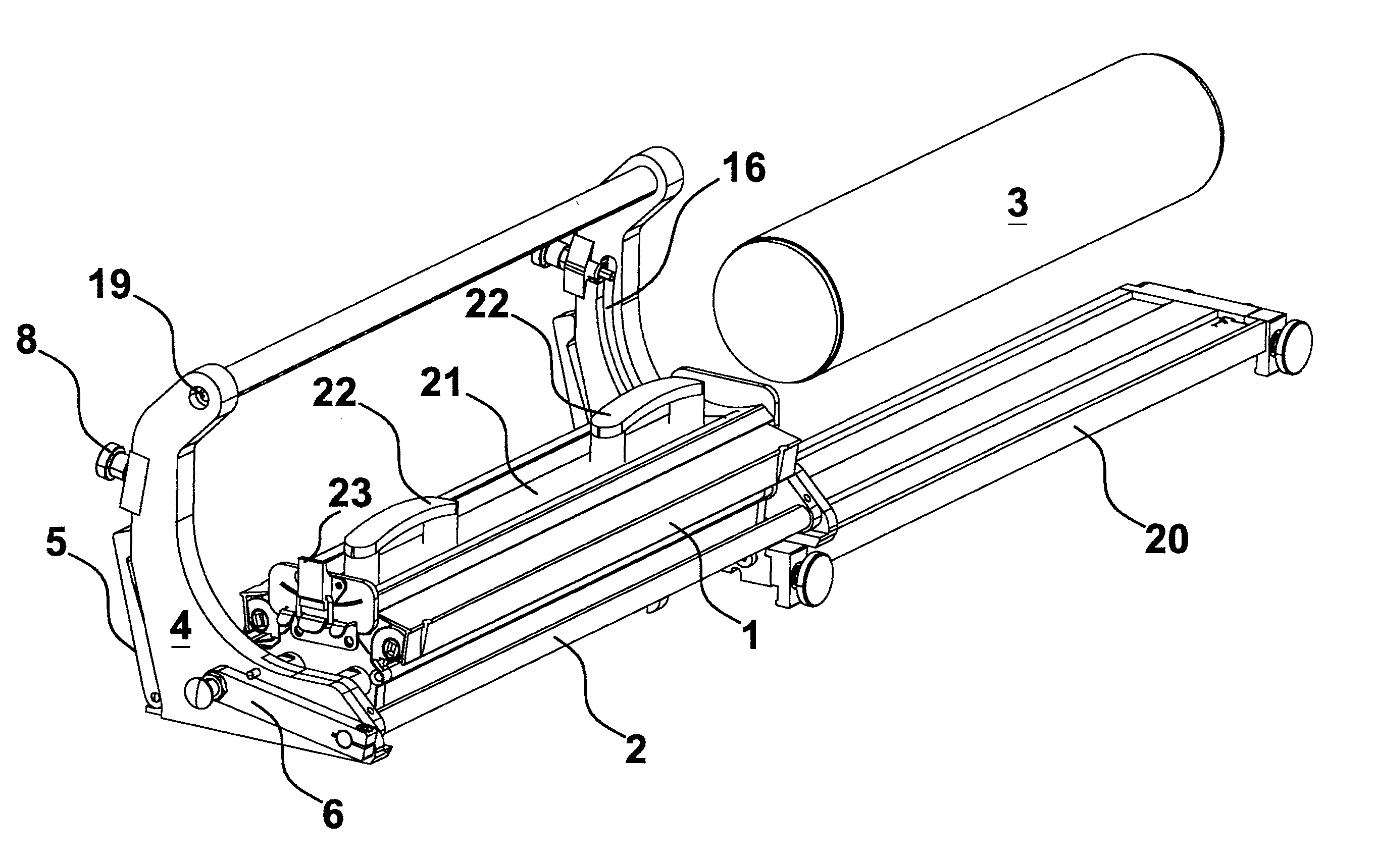
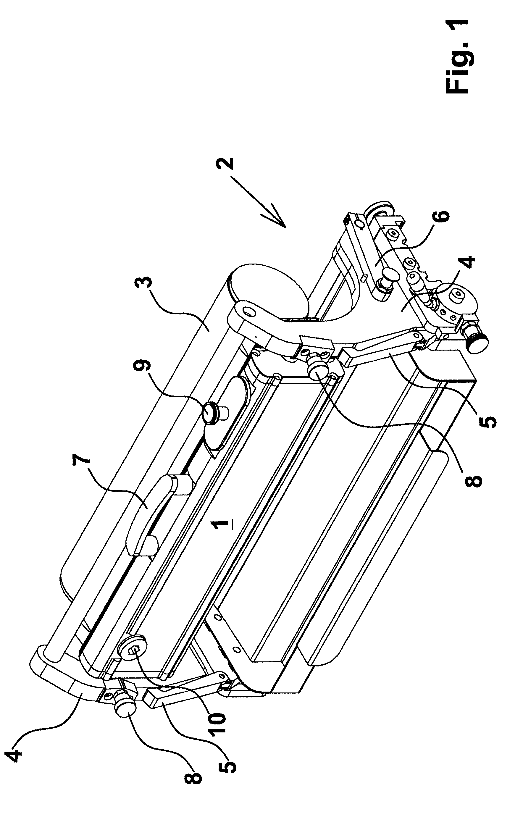
[0028]In FIG. 1 appears a doctor blade chamber 1 mounted in a support holder 2 in position of operation at a roller 3. The support holder 2 is adapted with not shown mounting grooves in which not shown guide pins guide the doctor blade chamber 1. The support holder 2 in the shown variant includes two end pieces 4 where the said mounting grooves are on the internal side. This will appear from a subsequent figure. At the bottom of the support holder on the two end pieces 4 are seen unfolding receiver arms 5 upon which the doctor blade chamber 1 is disposed before being moved into the not shown mounting grooves. When the doctor blade chamber 1 is moved into position under the roller 2, the doctor blade chamber is elevated, and the doctor blades are brought into contact with the roller 3 by an operating handle 6.

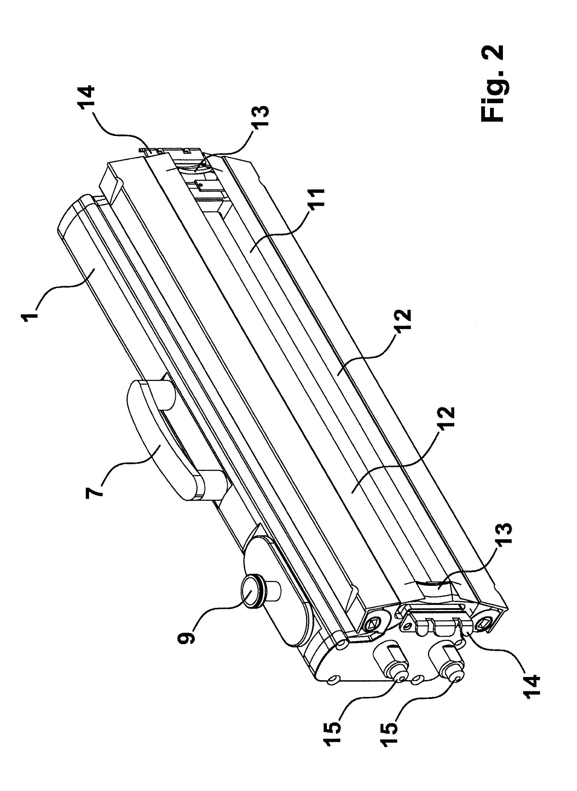
[0029]The doctor blade chamber 1 is provided with a handle 7 which is used during moving from a position under the roller 3 to the shown operative position in which it is retain...


PUM


Abstract

A method for mounting and dismounting a doctor blade chamber in a support holder on a printing unit as well as an apparatus in which the doctor blade chamber is placed in the support holder in a mounting position and subsequently is brought in contact with a roller, preferably, an anilox roller, in a position of operation. The method and the apparatus advantageously have the doctor blade chamber disposed with the opening upwards in the support holder, preferably in a horizontal position or in a position at such a small angle that ink does not run out of the doctor blade chamber, and is brought into a position under the roller, after which the doctor blade chamber is brought into contact with the roller and pivoted about an axis coinciding with the rotary axis of the roller, into the position of operation.

Description

BACKGROUND OF THE INVENTION[0001]1. Field of the Invention[0002]The present invention concerns a method for mounting and dismounting a doctor blade chamber in a support holder on a printing unit, where the doctor blade chamber is placed in the support holder in a mounting position and subsequently is brought in contact with a roller, preferably an anilox roller, in a position of operation. The invention furthermore concerns an apparatus including a doctor blade chamber and a support holder on a printing unit, where the doctor blade chamber is provided with fixing means for fixing in the support holder in a mounting position and subsequently in a position of operation wherein the doctor blade chamber is in contact with a roller, preferably an anilox roller.[0003]2. Description of Related Art[0004]It is commonly known that in connection with printing units a so-called doctor blade chamber is used from which ink / glue / varnish is applied to a roller, typically an anilox roller. In the fo...

Claims


Application Information

Patent Timeline
IPC IPC(8): B41F31/00
CPCB41F31/302B41F31/04
Inventor NIELSEN, MIKKEL QVIST
Owner TRESU
Why Eureka
Try Eureka