Wireless switch with multipolar electromagnetic generator

a multi-polar generator and wireless switch technology, applied in the direction of electromagnetic relay details, dynamo-electric machines, electrical apparatus, etc., can solve the problems of limited power output of piezoelectric energy, significant barriers to stand-alone use of conventional batteries, and difficulty in conversion without substantial losses

Inactive Publication Date: 2011-03-17
ECOHARVESTER
View PDF34 Cites 24 Cited by
  • Summary
  • Abstract
  • Description
  • Claims
  • Application Information

AI Technical Summary

Problems solved by technology

The average useful life of such a system is targeted to be more than 10 years, which means that the stand-alone usage of conventional batteries poses significant barriers to being a robust energy solution.
However, one problem is that thin-film piezoelectric energy have limited power output because of their high-voltage low-current output, typically tens of volts and less than nanoamperes, which makes it difficult to convert without substantial losses.
Another problem is the high intrinsic frequencies of piezoelectric (PZT) materials, typically around MHz, that can't be coupled to any vibrations or cyclical motion available for practical applications.
Electrostatic generators have limited power output similar to piezoelectric generators also due to the fact that they produce only high voltages and low electrical currents.
However, generating sufficient power at a desired compact scale has still not been achieved.
Further, the unmatched natural frequency of a small scale device, typically kHz, cannot be coupled to the vibrations that are commonly available for most applications.
Lastly, current designs require state-of-the-art precision machining and assembly (e.g., e laser cutting, electrical discharge machining (EDM), and CNC machining) or micromachining and thin film technologies (e.g., Magnetic materials, both permanent magnets and magnetic alloys, are difficult and expensive to do as thinfilms.
Micromachining in general gets expensive as the size of the device gets larger, and in this case the devices need to be relatively large (˜1 cm̂2) to give any reasonable amount of power.
At that size, micromachining becomes quite expensive.) that drastically raise manufacturing costs beyond that of batteries.

Method used


Image

  • Wireless switch with multipolar electromagnetic generator
  • Wireless switch with multipolar electromagnetic generator
  • Wireless switch with multipolar electromagnetic generator

Examples


Embodiment Construction

[0041]The invention can be implemented in numerous ways, including as a process; an apparatus; a system; a composition of matter; a computer program product embodied on a computer readable storage medium; and / or a processor, such as a processor configured to execute instructions stored on and / or provided by a memory coupled to the processor. In this specification, these implementations, or any other form that the invention may take, may be referred to as techniques. In general, the order of the steps of disclosed processes may be altered within the scope of the invention. Unless stated otherwise, a component such as a processor or a memory described as being configured to perform a task may be implemented as a general component that is temporarily configured to perform the task at a given time or a specific component that is manufactured to perform the task. As used herein, the term ‘processor’ refers to one or more devices, circuits, and / or processing cores configured to process da...


PUM


Abstract

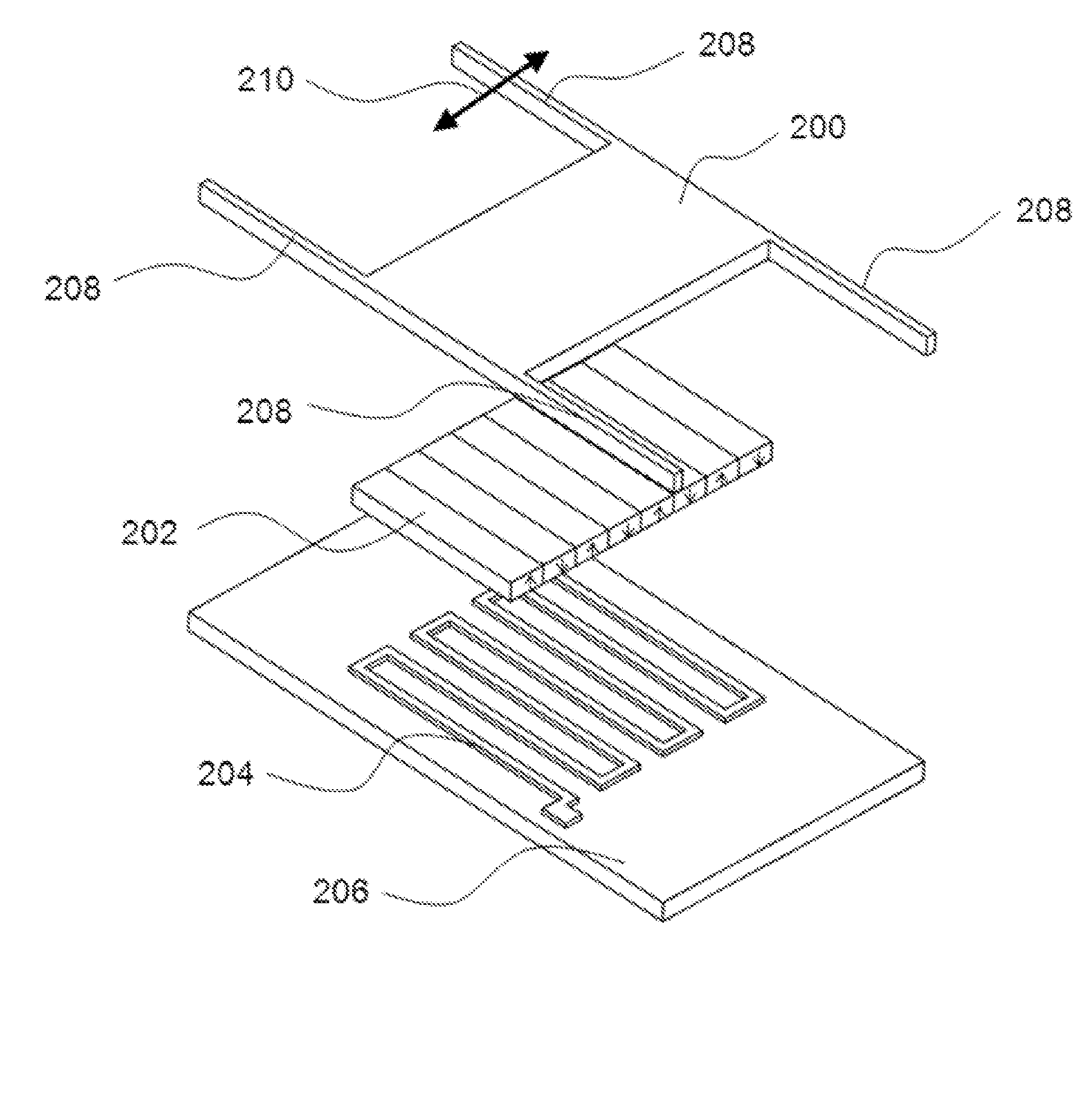
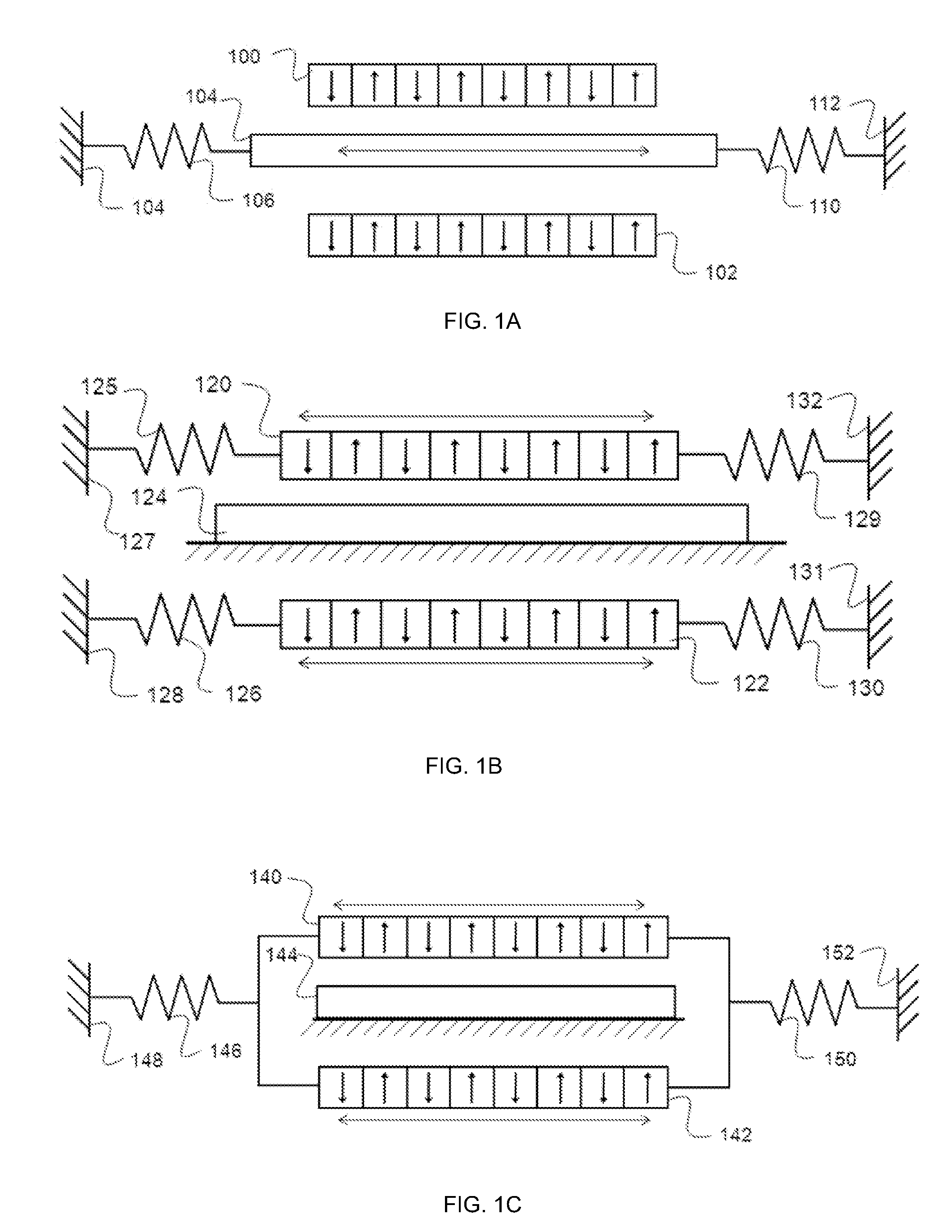
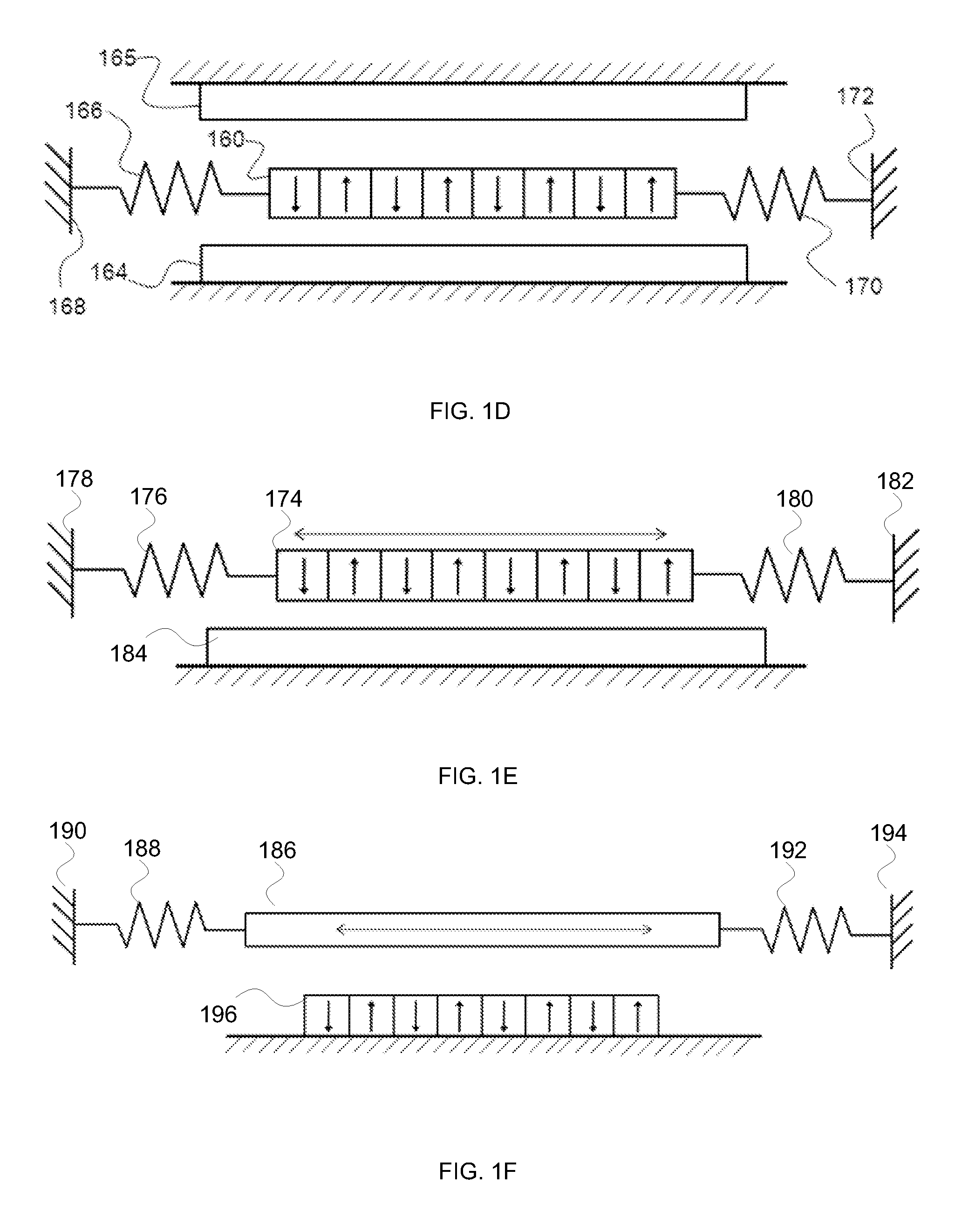
A wireless switch comprises a mechanical oscillator, a mechanical impulse deliverer, a first array of magnets positioned on a planar surface, a first conductor, and a power management circuit. The mechanical impulse deliverer delivers a mechanical impulse to the mechanical oscillator when the wireless switch is switched. The first array comprises a one dimensional or two dimensional array of magnets. The first conductor comprises a first serpentine conductor. The power management circuit provides DC power as a result of relative motion due to the mechanical oscillator between the first array of magnets and the first conductor.

Description

CROSS REFERENCE TO OTHER APPLICATIONS[0001]This application claims priority to U.S. Provisional Patent Application No. 61 / 242,805 (Attorney Docket No. ECOHP001+) entitled MULTIPOLAR ELECTROMAGNETIC GENERATOR filed Sep. 16, 2009 which is incorporated herein by reference for all purposes.[0002]This application claims priority to U.S. Provisional Patent Application No. 61 / 315,021(Attorney Docket No. ECOHP002+) entitled MULTIPOLAR ELECTROMAGNETIC GENERATOR FOR A SWITCH filed Mar. 18, 2010 which is incorporated herein by reference for all purposes.BACKGROUND OF THE INVENTION[0003]There are many sensor application areas where there is a clear need for innovative power solutions. The market for wireless sensor networks in industrial automation, supply chain management, construction, home automation, asset tracking and environmental monitoring is expected to grow to well over 400 million devices by 2012. The average useful life of such a system is targeted to be more than 10 years, which me...

Claims


Application Information

Patent Timeline
Patent Type & Authority Applications(United States)
IPC IPC(8): H01H9/00
CPCH02K35/02H02K35/00H02K35/04H01H50/54
Inventor TAKAHASHI, ERIROUNDY, SHADRACH JOSEPHTOLA, JEFFRYBIRCUMSHAW, BRIAN L.CARL, STEWART
Owner ECOHARVESTER
Why Eureka
Try Eureka