Sensor driving circuit, driver device, image reading apparatus, and image forming apparatus

a technology of driver device and sensor, which is applied in the direction of color television details, television system details, television systems, etc., can solve the problems of deficiency of characteristics such as transfer efficiency or noise, difficulty in satisfying signal timing, and difficulty in ensuring timing appropriately

Active Publication Date: 2011-03-17
RICOH KK
View PDF19 Cites 48 Cited by
  • Summary
  • Abstract
  • Description
  • Claims
  • Application Information

AI Technical Summary

Problems solved by technology

There may be cases where variation in threshold voltages, and difference in delay time of rise time (hereinafter, “rise delay time”) and in delay time of fall time (hereinafter, “fall delay time”) of a CCD driver that drives the CCD and variation in the difference are not negligible, making it difficult to secure timing appropriately.
Failure to satisfy these requirements may result in deficiency related to characteristics, such as transfer efficiency or noise.
As described above, even when signals are inputted via a single package driver, skew between different edges resulting from variation in difference between tpLH and tpHL remains large, which makes it difficult to satisfy signal timing.
It will be difficult to achieve operation speed higher than this.
Not only this variation, but also variation in threshold voltages of the DRV 4 may be a cause of skew.
As described above, the conventional technique is disadvantageous in that although the technique allows skew reduction when the skew is produced between same edges (e.g., a rising edge and a rising edge) of signals, on which timing requirement is imposed, the technique cannot attain skew reduction when the skew is produced between different edges (e.g., a rising edge and a falling edge) due to difference between rise delay time and fall delay time at a driver and variation in high-threshold voltage / low-threshold voltage of the driver.

Method used


Image

  • Sensor driving circuit, driver device, image reading apparatus, and image forming apparatus
  • Sensor driving circuit, driver device, image reading apparatus, and image forming apparatus
  • Sensor driving circuit, driver device, image reading apparatus, and image forming apparatus

Examples


Embodiment Construction

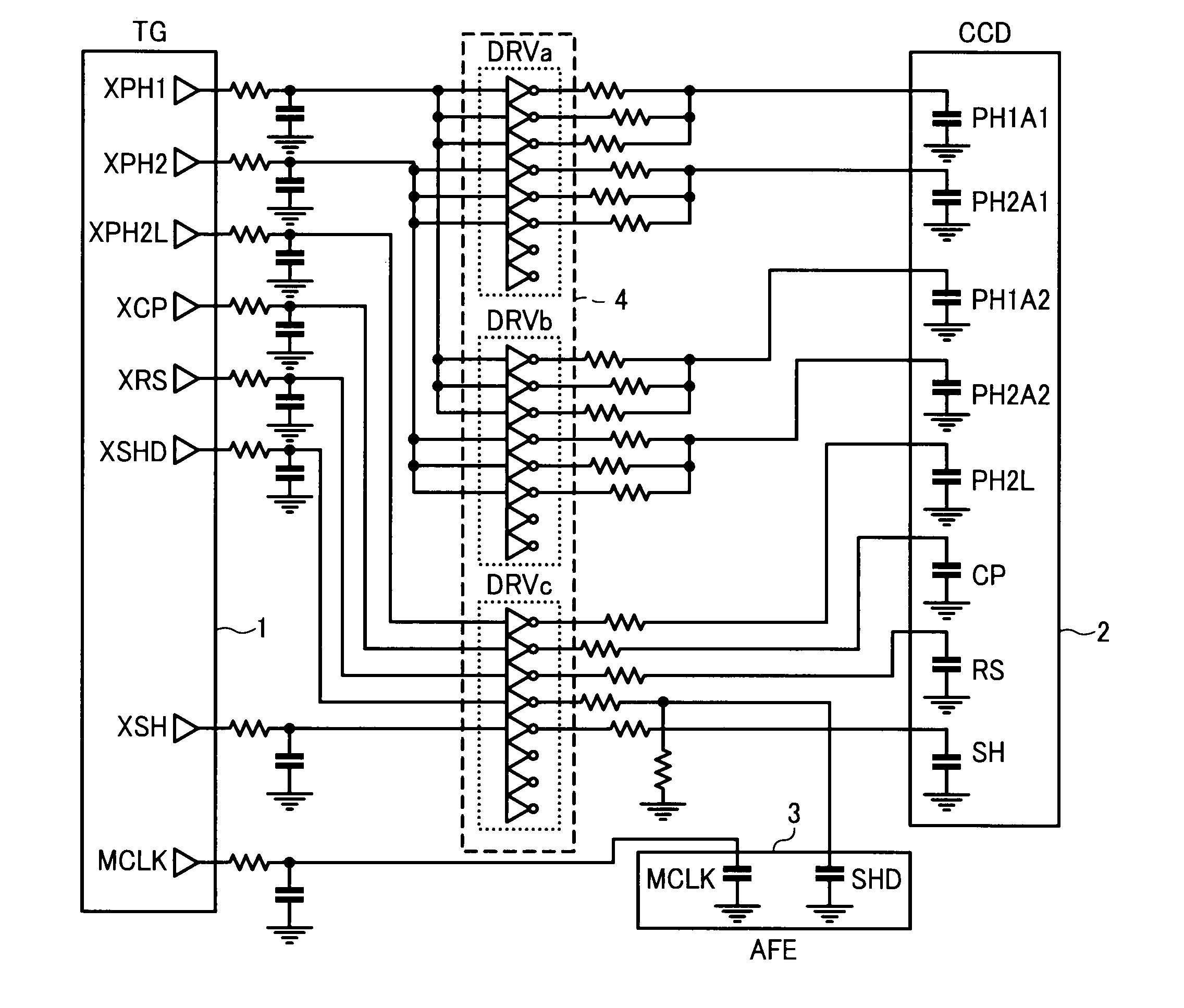
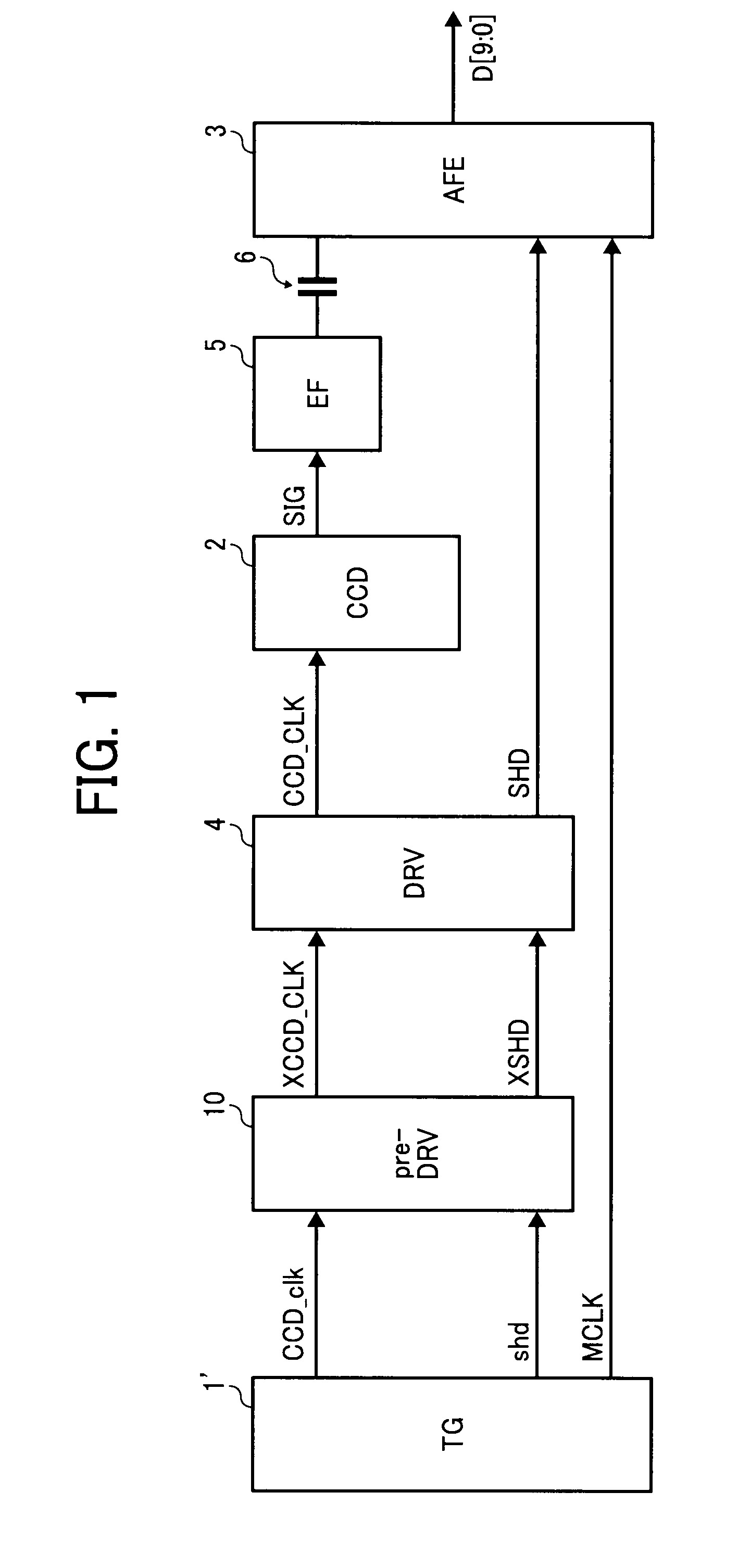
[0063]Exemplary embodiments of the present invention are described in detail below with reference to the accompanying drawings. FIG. 1 is a functional block diagram of a driving circuit that drives a CCD and an AFE according to an embodiment of the present invention. Elements and portions that are identical or correspond to those in FIG. 10 are denoted by like reference numerals and symbols.

[0064]In the configuration according to the embodiment illustrated in FIG. 1, an inverting driving circuit that is identical in configuration with the DRV 4 and that serves as a pre-driver (pre-DRV) 10 is additionally arranged at a preceding stage of the DRV 4 in the driving circuit illustrated in FIG. 10.

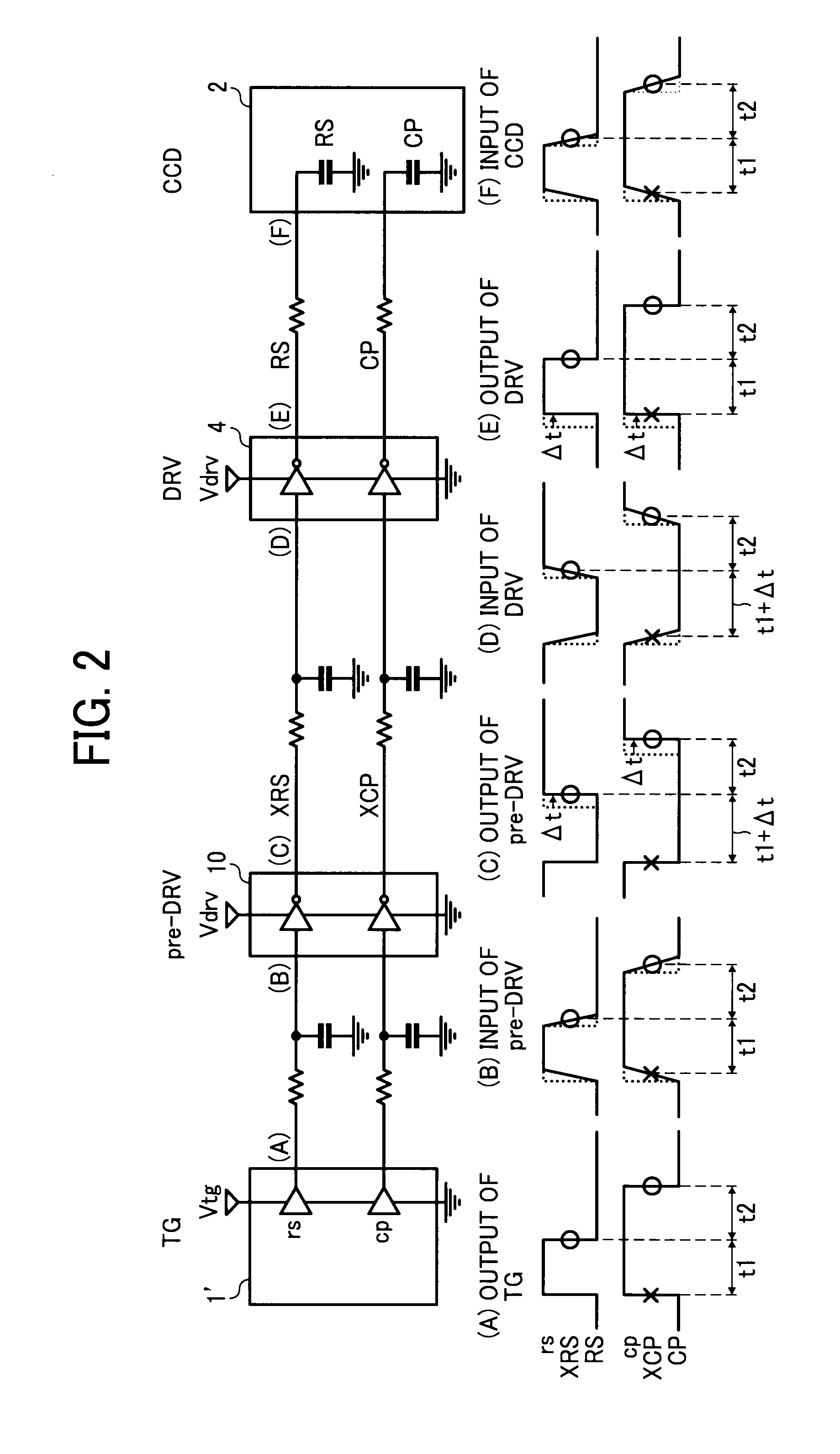
[0065]In the configuration illustrated in FIG. 1, unlike FIG. 10, polarities of a CCD-drive clock signal CCDclk and a sample / hold signal shd outputted by a TG 1′ are the same as the polarities of the signal that are inputted into the CCD 2 and the AFE 3. The polarities of an output signals of th...


PUM


Abstract

There is provided a sensor driving circuit that includes: an image sensor that converts light reflected from an original to be read into electric signals; a driver circuit that drives the image sensor; and a timing generator circuit that outputs timing signals for use in control of the image sensor. The driver circuit includes a first inverting buffer circuit and a second inverting buffer circuit that are equivalent to each other and arranged in series connection of two stages with the first inverting buffer circuit at the first stage of the two stages. The timing signal output from the timing generator circuit has the same polarity as the polarity of an input signal fed to the image sensor.

Description

CROSS-REFERENCE TO RELATED APPLICATIONS[0001]The present application claims priority to and incorporates by reference the entire contents of Japanese Patent Application No. 2009-210397 filed in Japan on Sep. 11, 2009.BACKGROUND OF THE INVENTION[0002]1. Field of the Invention[0003]The present invention relates to a sensor driving circuit, a sensor driver device, an image reading apparatus, and an image forming apparatus capable of decreasing influence of skew among signals having different edges.[0004]2. Description of the Related Art[0005]Charge-coupled device (CCD) line image sensors (hereinafter, referred to as “CCD”) have been employed in an image reading apparatus as photoelectric converter for reading images of an original. There may be cases where variation in threshold voltages, and difference in delay time of rise time (hereinafter, “rise delay time”) and in delay time of fall time (hereinafter, “fall delay time”) of a CCD driver that drives the CCD and variation in the diff...

Claims


Application Information

Patent Timeline
Patent Type & Authority Applications(United States)
IPC IPC(8): H04N5/335
CPCH04N5/3765H04N5/372H04N25/71H04N25/745
Inventor NAKAZAWA, MASAMOTO
Owner RICOH KK
Why Eureka
Try Eureka